Microscope Stages
Microscope stages, also known as XY microscope stages, are platforms that hold and move a sample in x and y motion, enabling precise positioning and observation under a microscope. These stages come in various types, such as rotating stages, motorized stages, and translation stages. Depending on the direction of movement, microscope stages are classified into XY stages and Z focusing stages.
At Dover Motion we have created a unique microscope stage architecture by embedding high-performance precision electronics required to control motion within the stage without increasing its size. Explore our range of microscope stages below.


The DOF-5™ stage is optimized for objective focusing with increased travel, higher bandwidth, and lower cost than piezo stages.
| wdt_ID | Travel | 5 mm |
|---|---|---|
| 1 | Resolution | 1.25 nm |
| 2 | Repeatability | < 50 nm |
| 3 | Bandwidth | > 225 Hz |

The award winning SmartStage™ XY stage offers high precision and includes an embedded controller inside the stage.
| wdt_ID | Travel | 50 - 200 mm |
|---|---|---|
| 1 | Accuracy | ≤ 10 μm |
| 2 | Repeatability | 0.5 μm |
| 3 | Payload | up to 6 kg |

Custom Microscope Stages Capabilities
Dover Motion has more than 25 years of experience working with OEMs to optimize motion for automated digital microscopy including objective focusing and moving samples on slides, well plates, or flow cells.
Our engineers developed unique motion control architectures for precision motion systems specifically tailored to the needs of OEMs developing microscope-based systems and instruments relying on optical imaging as the analytical detection technique.
Whether your project requires a customization to a standard product or a completely custom microscope stage design, we’ll collaborate with your team to ensure we hit the most challenging design, cost, and schedule targets.

Gene Sequencing Imaging Sub-Assembly
- XY Stages moving a flow cell
- Z stage for objective focusing
- Integrated laser autofocus
- Automated Rotary filter changer
Speak with an Engineer about your custom application.

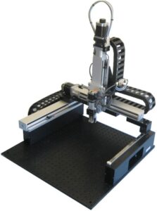
SmartStage Open Frame (SS-OF)
- Fast Linear Motors
- Built in controller
- High Resolution encoder feedback
Speak with an Engineer about your custom application.

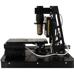
Microscope Demo
- DOF-5 Objective focusing
- Linear Motor XY for slide positioning
Speak with an Engineer about your custom application.
"The SmartStage XY linear motor stages surprised us with their speed and silence. They have handily met our need for fast, accurate movements, and long holding stability. We love the internally protected optical encoders, making the stages more reliable and easier to work with."
- Associate Director of Engineering, Life Science OEM
See How We are Disrupting Motion Control


Microscopy Learning Center
We’ve created this library of resources to connect you the latest information on microscopy and to guide you to expert insights, product documentation, and reviews of key concepts and considerations that will accelerate your next discovery or breakthrough.
Whitepapers
This whitepaper provides an introduction to the SmartStage™ XY platform and a comparison to alternative technologies to show why this technology is already transforming automated digital microscopy.
Optimize the performance and cost of your automated optical imaging system with 6 key equations for selecting an imaging sensor, objective lens, Z-focusing nano-positioning stage and XY sample positioning motion.
This white paper addresses high performance Z axis focusing for automated microscopy, along with some recent innovations in this space.
Case Studies
Through concurrent and collaborative engineering, Dover Motion designed a compact custom XYZ stage solution to produce high-precision cell imaging in parallel with the instrument design.
Dover Motion worked closely with Invetech to define the motion system requirements and tightly integrate the hardware in the overall instrument design.
Videos
View some of our educational videos here.
Topics that will be covered are selecting the right type of sensor and sensor size, magnification, field of view, pixel size, resolution, depth of field, and numerical aperture for digital microscopy.
Depth of field is an important criteria for selecting the precision and resolution of focusing stages for automated imaging applications. This video explains what depth of field refers to for objective focusing.
When designing complex systems, there are a lot of options to consider. In this video, we explain the XY stage for sample positioning, and Z stage for precision microscope objective focusing motion.
This video covers key formulas for selecting the optimal imaging sensor and microscope objective for your digital imaging application.
Anatomy of a Microscope

Tube Lens: An optical element that focuses the parallel light of an infinity corrected objective onto the image sensor surface.
Illumination Source: The illumination source sends light to the reflective mirror to illuminate the sample in epi-fluorescence imaging.
Objective Lens: The primary optical component of an imaging microscope, and responsible for magnification and focusing when moved relative to the sample.
Peltier Heater/Cooler: Helps modulate the temperature of the sample and ensures fast and precise temperature switch.
Camera: A central part of the automated digital microscope which has an image sensor to convert the reflected light into a digital image.
Turret/Rotary Filter Changer: A sub-assembly that mounts several objectives or fluorescent filters which can then be either manually or automatically rotated into position.
Laser Autofocus Hardware: Emits a beam of light from which the distance to the object can be determined and the correct focus or image point of a selected area is identified.
Filter Cubes: Allows specific wavelengths of light to pass through to permit high contrast fluorescent imaging.
Flow Cell Sample: The specimen that will be inspected, imaged, and analyzed by the automated digital microscope. Other sample types include slides, well plates, and custom microfluidic chips.
XY Stage: Used to position the sample (slides, flow cells, well plates, etc.) being imaged or analyzed under a microscope allowing motion in two degrees of freedom.
A digital microscope uses a digital camera rather than a traditional eyepiece. An image of the sample is observed and analyzed directly on an electronic monitor display in real time.
Modern biomedical, life science and diagnostic instruments rely on automated digital microscope technologies. DNA sequencers, cell imaging instruments, and digital pathology scanners are just a few of the many applications for digital microscopy solutions. When designing these complex systems, there are a lot of options to consider which involve tradeoffs in performance, throughput, and cost.
The functions of a digital microscope are to control the digital camera, illumination and filter selection. In addition, microscopes require two critical positioning functions. The first is to precisely position the sample on the microscope slide in the XY plane. This can either be done with fast moves between adjacent fields (field sequential imaging), or stable constant velocity motion (scanning imaging). The second key positioning task for a microscope stage in an automated microscope is the focus axis. This moves the objective relative to the sample to maintain critical objective focus at all times.
Digital microscopes are designed to include stages which move a sample or objective in x, y, or z motion. We’ve created a unique microscope stage architecture by embedding high performance precision electronics required to control motion within the microscope stage without increasing its size.
Microscope stages move a sample or objective in x, y, or z motion and are typically available as either single axis, an XY stage, or XYZ stages. Microscope stages are also commonly referred to as XY tables, linear actuators, motorized stages, or linear translation stages.
XY motion is performed by an XY microscope stage, which is typically a thin, low-profile stage with a central opening for the transmissive imaging. XY microscope stages are typically actuated with stepper motors and lead screws, while cutting-edge designs employ a linear motor and a linear encoder on each axis and close a servo feedback loop.
Automated microscope focus axes typically use piezo or direct drive technology. In a microscope stage, direct drive linear motors offer extended range, allowing the objective to be retracted during sample load and unload, together with very high resolution and repeatability. The focus axis position is typically commanded by an autofocus sensor, which derives a focus error signal via a laser diode passing through the objective or by a software autofocus algorithm.
Once the optical imaging elements are selected, the mechanical microscope stage architecture can be finalized. A typical field of view is much smaller than the sample being imaged. Thus, in order to image an entire sample, either the sample or the camera/objective will need to move along two perpendicular axes (XY). In addition, in order to properly resolve the image, the distance between the magnification objective and the camera (or image sensor) needs to be precisely adjusted. This is referred to as the Z axis. The Z axis is typically vertical and motion along it occurs perpendicular to the XY plane to move the sample into the imaging field of view.
The microscope field of view calculation relates the sensor size to the magnification and will determine how many XY movements will be required to image the area of interest on the sample.
There are three common configurations of the mechanical microscope stage motion hardware. Selecting the best one depends upon the complexity of the particular application.
- The XY microscope stage moves the sample below a Z stage that is moving the objective or camera. This is the most common configuration. The benefit of this approach is that the image becomes stable after motion more quickly because the microscope slide is only moving on one motorized axis. This means it can be mounted to a sturdy structure instead of a stack of three moving axes whose resonances need to damp. During sample loading, the objective can be moved vertically away from the sample mounting area, which makes changing samples easier. Also, Abbe errors are reduced because the overall stack is shorter. To understand the impacts of Abbe errors on stage positioning, see our Abbe error white paper. This method works for regular or inverted microscope configurations.

- Three motion axes move the object being imaged in X, Y and Z directions while the camera and objective remain stationary. In this situation, the camera is very stable because it is mounted to a rigid surface. The drawback is that the travel required for the Z axis may be longer because the objective-to-imaging sensor distance is fixed. Typically, it requires less travel to move the objective with respect to the imaging sensor or camera.
- The objective or camera is moved in X, Y and Z directions, while the sample remains fixed. This approach works best when imaging small parts such as a microscope slide. As part size increases, the complexity of this approach also increases. Larger travels tend to require two axes to support a beam that has the vertical focus axis with both the imaging sensor and objective mounted to it.