Interferometer Feedback Systems
Laser interferometers provide the ultimate in position feedback, combining very high resolution, non-contact sensing, high update rates, and intrinsic accuracies of 0.1 ppm.
They can be used in positioning systems as either passive position readouts, or as active feedback components in a position servo loop. Unlike linear encoders, the interferometer beam path can usually be arranged to coincide with the item or point being measured, eliminating, or greatly reducing errors due to Abbé offset.
Laser interferometers can be divided into two categories: fringe counting and two-frequency systems. The former is similar in operation to a Michaelson interferometer while the latter uses two closely spaced frequencies, one of which experiences a Doppler shift from the moving reflector. Upon recombination, the two frequencies are heterodyned to generate a beat frequency within the range of counting electronics. The two frequency design, while more costly to implement, is considered the higher performance system, especially for velocity feedback. In both cases polarization selective optics are used to route one beam to and from the moving workpiece while retaining a fixed path for the reference beam.
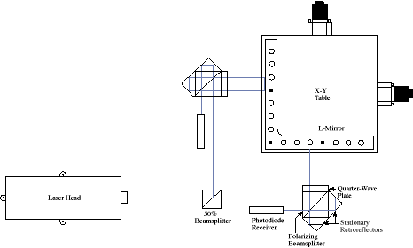
Single-axis systems utilize a beam path as shown in Figure 24a and consist of the laser head, polarizing beamsplitter with retroreflector, the moving retroreflector, and a photodiode receiver. XY systems (Figure 24b) replace the moving retroreflector with a plane mirror and add a quarter-wave plate and an additional retroreflector to the separation optics. The quarter-wave plate circularly polarizes the workpiece beam, causing it to perform two passes, with a corresponding doubling of resolution and halving of achievable top speed. This configuration eliminates errors due to Abbé offset, yaw, and opposite axis horizontal runout, and ignores orthogonality errors in the X-Y tables (the plane mirrors, however, must be precisely square to each other). The reflectors can consist of two “stick mirrors” in adjustable mounts, or a single “L mirror” (as shown in the photo). The latter eliminates concerns over stick mirror misadjustments but carries cost penalties which grow rapidly with increasing travel.

Figure 24a – Single-Axis Interferometer Beam Path

Figure 24b – Two-Axis Interferometer Beam Path
As the N.B.S. (now N.I.S.T.) pointed out in the mid-seventies, any He-Ne laser provides frequency stability equal to or better than 1 part in 106, 1 ppm (any greater error would inhibit the lasing process due to the narrow neon line width). Frequency stabilization systems can improve this, achieving accuracies of better than 1 part in 107 (0.1 ppm). The following error sources, however, conjoin to degrade this very high intrinsic accuracy:
- Speed of light variations due to temperature, pressure, etc.
- Pressure, temperature and humidity sensor accuracy
- Plane mirror squareness and flatness
- Thermal expansion of workpiece, positioning table, base plate and interferometer optics
- Cosine error
- Accuracy of workpiece thermal expansion coefficient
- Differential flexure of positioning table top through its travel
- Edelin and Jones equation accuracy
- Accuracy of deadpath value
While the individual contributions of these effects may be small, their aggregate effect on error budgets can be significant. Attempts to wring increasing accuracy from a positioning system rapidly degrade into elaborate thermal management exercises. Our accuracy claims, while modest in light of industry practice (ads claiming “tenth micron accuracy” from open loop or encoder-based products are particularly amusing), are based on reasonable estimation of the consequences of a number of error sources. In some applications, however, a number of the above error sources can be side-stepped. One such application is a wafer positioning stage, where fiducials on each wafer can be located to high precision, and used to align the lasers X-Y coordinate frame to the wafer frame for the duration of a single set of measurements (typically several minutes or less). Our Applications Engineers can be relied upon to produce realistic estimates of the achievable accuracy in your specific application. For a more detailed discussion of interferometer based positioning, including four-pass and differential interferometers, wavelength compensators, etc., see our White Paper, “Accuracy in Positioning Systems“.
Motion Control Handbook
Abbé Error
Accuracy in Positioning Systems
Constant Velocity
Cosine Error
Full Coil vs. Half Coil
Glossary of Terms
High Vacuum Positioning Tables
Interferometer Feedback Systems
Interpolated Motion
Lead Screws and Ball Screws
Linear Motors
Limit Sensors
Limitations of Piezos
Low Magnetic Field Tables
Linear Positioning Accuracy
Mapping
Microstepping
Midrange Resonance
Motion Calculations
Mounting Issues
Move and Settle Time
Positioning Systems Overview
Repeatability
Resolution
Rotary Motor Mount
Servo Motors
Slow Down to Speed Up
Stepper Motor
Thermal Expansion
Torque and Force Requirements
Units of Measure
Vibration Isolation Systems
