Accuracy in Positioning Systems
The state of the art in precision positioning systems has undergone continuing improvement, with the result that modern positioning systems can now achieve unprecedented levels of accuracy. Notwithstanding the gains that have been made, there are gaps between levels of accuracy which are perceived as achievable, and those levels which can actually (and/or affordably) be met. We’ll address the realistic accuracy levels which various positioning technologies can meet, as well as the nature of the limitations which restrict accuracy.
What is “ACCURACY”?
Dimensional accuracy is simply the degree to which displacements executed by a positioning system match agreed upon standards of length. Ultimately, all length measurements are tied to the meter, as defined by the Committee Consultif pour Definition du Meter. Its current value is the distance which light in a vacuum travels in 1/299,792,458 of a second. When describing accuracy, we employ a variety of units considerably smaller than a meter. These include the familiar millimeter (10-3 meter), micron (10-6 meter), nanometer (10-9 meter), Angstrom (10-10 meter) & picometer (10-12 meter). For comparison purposes, a human hair is about 100 microns in diameter, semiconductor line widths are about 1 micron, and an atom is about 1 Angstrom.
“FUZZ” vs. “BUNK”
The heading, while somewhat jocular in nature, reflects a widespread lack of seriousness with respect to accuracy claims. Positioning system purchasers prefer that accuracy be summarized in a single, easily digestible number (and the smaller, the better). Positioning system vendors, in turn, comply; the unfortunate results include a recent full page ad which claimed to extract “tenth micron accuracy” from an open loop stepper based system. When questioned, an applications engineer responded that they were using a 1 mm leadscrew, and a divide-by-50 microstepper; hence, “tenth micron accuracy”. Examples such as these reflect either a profound lack of awareness of the meaning and limitations of high accuracy systems (“fuzz”), or an overly aggressive marketing of “small numbers” for competitive advantage (“bunk”). Common practices include defining stage accuracy as equal to that of the purchased leadscrew incorporated in the stage, ignoring thermal factors and Abbé error; mentioning the accuracy of multi-axis systems without a “per axis” qualifier; providing accuracy values which reflect only the no-load value, etc. The fact of the matter is that accuracy is affected by a combination of positioning stage attributes; control and feedback systems; application specific details (e.g., the height above the stage of the point of interest); as well as the operating environment. A meaningful characterization of system accuracy is better achieved by a complete analysis than by an attention grabbing “number”.
The 6 Degrees of Freedom in Motion
Positioning system accuracy can be conveniently divided into two categories: 1) the accuracy of the linear bearing itself, and 2) the linear positioning accuracy along the bearing. The former describes the degree to which the ways / bearings (ball and rod, crossed roller, air bearing, etc.) provide an ideal single axis translation, while the latter is concerned with the precision of incremental motion along the axis (typically related to the leadscrew, linear encoder, or other feedback device).
Any moving object has six available degrees of freedom (Figure 2). These consist of translation, or linear movement along any of three perpendicular axes X, Y, and Z, as well as rotation around any of those axes (Θx, Θy, Θz). The function of a linear positioning way is to precisely constrain the movement of an object to a single translational axis (typically described as the X axis). Any deviations from ideal straight line motion along the X axis are the result of inaccuracy in the bearing assembly.
There are five possible types of way or bearing inaccuracy corresponding to the five remaining degrees of freedom (Figure 3): translation in the Y axis; translation in the Z axis; rotation around the X axis (roll); rotation around the Y axis (pitch); and rotation around the Z axis (yaw). Since there are interrelations between these errors (angular rotation, for example, produces a transitional error at any point other than the center of rotation), it is worthwhile to carefully examine the effects of each type of error and its method of measurement.
Since all useful methods of producing linear motion average over a number of points (due to multiple balls or rollers in a bearing, or the area of an air bearing), “pure” translational errors from straight line motion (that is, without any angular error) are usually minor.
What Causes Runout?
Positioning stages exhibit some vertical and horizontal run out (typically referred to as errors of flatness and straightness, respectively), as can be measured by placing a sufficiently sensitive indicator on a stage and measuring the vertical or horizontal displacement along its travel. An exaggerated sine wave error in rolling element ways could achieve a pure translational error without rotation, as would be the case of each roller in a bearing way running over a contaminant particle at the same time. If a rolling element stage has been subjected to a large impact, the ways may be brinelled (dented) at each ball or roller location; this can result in a pure translational error that occurs periodically along the travel.
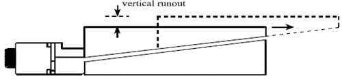
With the following exception, these transitional errors are the consequence of underlying angular errors, as described below. In the example of figure 4, the bearings are perfectly straight and allow only translation along a single axis. Since, however, our desired X axis of motion is usually defined as parallel to the base of the stage, and the ways are inclined relative to that base, the indicator will see a rise and fall as the stage travels back and forth. While the bearings may be ideal, their orientation within the stage can result in translation along the Z axis (also called vertical runout, or an error of flatness). There is no basis for a corresponding effect in the Y axis since the exterior sides of positioning stages are not commonly assumed to include a reference surface.
The angular errors of roll, pitch, and yaw (Θx, Θy, and Θz, respectively) are always present at some level in positioning stages and degrade performance in several ways. Their direct effect is to vary the angular orientation of a user payload. Due to the relative care with which these errors can be maintained at low levels (2-40 arc seconds), they are of little consequence ‘in many applications. Certain optical positioning tasks, however, may be directly impacted by angular errors.
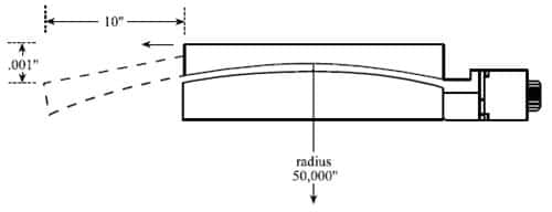
Of somewhat greater concern are the translational errors resulting from underlying angular errors. The simple pitch error shown in Figure 5, corresponding to a radius of curvature of 50,000 inches, will produce a Z axis translation of .001″ in a 20″ travel stage at either end of travel, relative to its centered position. Such simple pitch errors are typically found in non-recirculating stage designs, due to the overhanging nature of the load at both extremes of travel. More complex curvatures involving roll, pitch, and yaw, as well as multiple centers of curvature, can also be encountered.
The worst impact of angular errors is the resulting Abbé (offset) error which affects linear positioning accuracy. Unlike the simple translational error described in the above example, Abbé error increases as the distance between the precision determining element and the measurement point increases.
Positioning stage runout errors can be divided into two categories:
- A low frequency component
This is rarely a “pure” translational error, but is rather a consequence of the underlying angular errors (pitch, roll, and yaw) in the bearings. Since the moving portion of the stage follows (at some level) a curved trajectory, there is a corresponding linear deviation from a straight line. The angular and linear errors correlate quite well, and one can be obtained from the other by the process of integration or differentiation. - Higher frequency components, which can arise from a variety of sources, not necessarily errors of the bearings.
A once-per-revolution rise and fall of the table top can occur near each end of travel if a ball screw is used. The use of flexurally coupled nuts and/or friction nuts can reduce this effect. Additional sources of higher frequency flatness errors can include microstructure in the ways or rolling elements, drive and/or motor induced vibration, and structural resonances in the stage top. Since a number of optical positioning applications have limited depths of field, it is important to understand the magnitude of each of the above effects, and to modify the stage design so as to minimize the effects. The bearing and motor selection is critical to stage runout performance.
Accuracy, Repeatability, and Resolution: What’s the difference?
These three terms are the fundamental parameters of positioning systems. Unfortunately, they are often used synonymously with resulting confusion on the part of users and suppliers alike.
Resolution is frequently defined as the smallest positional increment which can be commanded of a system; a more rigorous definition would modify this to reflect the smallest positional increment which can be realized. Open loop or rotary-encoded servo systems are capable (depending on leadscrew pitch) of providing useful resolutions of as low as 0.1 micron. The use of a linear feedback encoder, together with a servo loop incorporating an integrator (the “I” in P-l-D), allows useful resolutions below 0.01 microns (10 nanometers).
The repeatability of a positioning system is the extent to which successive attempts to move to a specific location vary in position. A highly repeatable system (which may or may not also be accurate) exhibits very low scatter in repeated moves to a given position, regardless of the direction from which the point was approached. The images below illustrate the difference between repeatability and accuracy.

Click the link for a more detailed explanation of repeatability. For examples of how to determine resolution see this Resolution handbook page.
Motion Control Handbook
Abbé Error
Accuracy in Positioning Systems
Constant Velocity
Cosine Error
Full Coil vs. Half Coil
Glossary of Terms
High Vacuum Positioning Tables
Interferometer Feedback Systems
Interpolated Motion
Lead Screws and Ball Screws
Linear Motors
Limit Sensors
Limitations of Piezos
Low Magnetic Field Tables
Linear Positioning Accuracy
Mapping
Microstepping
Midrange Resonance
Motion Calculations
Mounting Issues
Move and Settle Time
Positioning Systems Overview
Repeatability
Resolution
Rotary Motor Mount
Servo Motors
Slow Down to Speed Up
Stepper Motor
Thermal Expansion
Torque and Force Requirements
Units of Measure
Vibration Isolation Systems