Microstepping
An important variation on conventional stepping motor drives is that of microstepping.
Conventional bipolar drives alternate the current direction in one coil at every step, resulting in a rotor displacement of 1.8 degrees. In microstepping, the coil current is changed in much smaller increments, increasing in one coil as it decreases in the other. The rotor responds by swinging to its new magnetic equilibrium, which can be a small fraction of a full step.
Microstepping has two principal benefits: it provides increased resolution without a sacrifice in top speed, and it provides smoother low speed motion. For example, to achieve a resolution of 5 microns with a full step system requires the use of a screw with a 1.0 mm lead. This places substantial constraints on top speed. A shaft speed of 40 revolutions per second results in a linear velocity of only 40 mm per second. Use of a divide-by-10 microstepper provides the same 5 micron resolution with a 10 mm leadscrew, but the linear velocity in this case is now 400 mm per second. Alternately, the resolution can be increased, to 0.5 micron with a 1 mm lead, or 1.0 micron with a 2 mm lead.
Operation at low step rates (especially near the fundamental resonance) generates noise and vibration, since stepping motors, by definition, move in discrete angular increments. Microstepping decreases the size of these increments, and increases their frequency for a given rotation rate. This results in significantly smoother low speed operation. A laser interferometer was used to produce the graphs in Figures 33a-d, which show the reduction in positional oscillations and velocity ripple for a positioner at a low (0.05 revolution/second) step rate.

Figure 33a – Full Step Position vs. Time
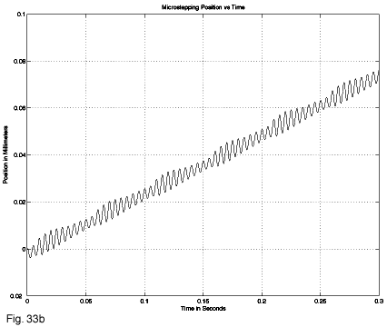
Figure 33b – Microstepping Position vs. Time

Figure 33c – Full Step Velocity Deviation

Figure 33d – Microstepping Velocity Deviation
Despite the apparent benefits of microstepping, it is frequently implemented with excessive degrees of subdivision. A key attribute of many commercial systems is “empty resolution”, where the apparent microstepping resolution can not be achieved. The torque which any microstep generates is found as follows: torque per microstep = motor holding torque x sine (90 degrees/S.D.R.), where S.D.R. is the step division ratio.
In the case of 50,000 step/revolution systems, the S.D.R. is 250, and each microstep produces a torque change of 0.3 oz-in (with a standard 53 oz-in motor). Most high repeatability, preloaded leadscrew systems have torques in the 3-6 oz-in range; accordingly, 10-20 microsteps must be taken before the torque builds to a level which results in leadscrew motion. Direction reversals behave similarly; what appears to be backlash in the positioning table is actually excessive microstepping resolution. High division ratios have the additional effect of limiting the achievable top speed, by the inability to produce very high speed pulse trains (100 revolutions per second at 50,000 steps per revolution requires 5 MHz ramped pulse trains).
We have chosen a standard microstepping division level of 10; this provides 2000 microsteps per revolution, matching the resolution of our built-in rotary encoders. The resulting torque per microstep of 3 oz-inches is also a close match to existing leadscrews, providing a tight coupling of command and response. For systems which require higher resolution, we offer an optional division level of 50. This is as high a value as is practical, and requires pulse rates of up to 1 MHz, but provides exceptional speed and resolution: 0.25 microns with a 400 step/revolution motor and a 5 mm leadscrew.
Motion Control Handbook
Abbé Error
Accuracy in Positioning Systems
Constant Velocity
Cosine Error
Full Coil vs. Half Coil
Glossary of Terms
High Vacuum Positioning Tables
Interferometer Feedback Systems
Interpolated Motion
Lead Screws and Ball Screws
Linear Motors
Limit Sensors
Limitations of Piezos
Low Magnetic Field Tables
Linear Positioning Accuracy
Mapping
Microstepping
Midrange Resonance
Motion Calculations
Mounting Issues
Move and Settle Time
Positioning Systems Overview
Repeatability
Resolution
Rotary Motor Mount
Servo Motors
Slow Down to Speed Up
Stepper Motor
Thermal Expansion
Torque and Force Requirements
Units of Measure
Vibration Isolation Systems