Move and Settle Time
Many applications emphasize throughput, and accordingly seek to minimize the move and settle time required for point-to-point moves. One of DOVER‘s differentiating characteristics is our ability to provide in-depth mathematical analysis of the dynamic behavior of our stages.
We have developed extensive Mathcad and MathLab® spreadsheets which model and predict the performance of our positioning stages. To measure the dynamic response of our tables, and provide real-world feedback to our models, we use a tool with both high spatial and temporal resolution: the laser interferometer. Its combination of 1.25 nanometer resolution, 100 kHz position update rate, and non-contact optical position sensing are ideal for examining stage dynamics. We have written software which samples the laser interferometer at variable rates to 100 kHz, and the resulting data file is analyzed using Mathcad and MathLab® to reveal specific details of the system dynamics.
It is important to note that it is meaningless to specify either a move and settle time, or simply a settling time, without also providing a position window within which to settle. The first entry into this target window does not necessarily define the completion of the move and settle, as subsequent ringing may move the payload outside the window. Move completion is defined when the position is within the target window, and it remains there until the next move. In general, the smaller the target window is defined, the longer the move and settle time will be.
Move Time The move and settle time for a given application can be conveniently separated into two halves: the move time, and the settling time. The time required to make a given move is a function of the commanded move trajectory, the available torque or force, and the inertia and friction of the load. The move trajectory includes the acceleration and deceleration profiles, the percent of the move spent at constant velocity, and the top speed which can be achieved. Short moves may never reach top speed, and will simply consist of an acceleration and deceleration phase. When stepping motors are used to drive a stage, the fact that their available torque falls off with speed requires either that a lower acceleration be commanded, or that the acceleration be decreased as the shaft speed increases. Stepping motors also have a very noticeable way of letting you know that they have inadequate torque for a given application – they stall. Once a specific acceleration profile and top speed have been selected, either by consulting a model or by empirical testing, the move time for any given move distance is easily calculated. The position to which stepping motor driven stages settle may not be the precise one desired, since they are open loop devices and are susceptible to things like lead screw error. A linear encoder can be added, and it can be interrogated at the end of the move to see if a small corrective move is in order; the next obvious step is to a servo system. For rotary or linear servo motors, linear acceleration trajectories are typical, although an “S curve” profile may be used to minimize jerk. At low duty cycles, servo move times are limited by the available electrical resources (amplifier current and voltage), or by the risk of de-polling the permanent magnets of the motor. At high duty cycles, thermal limits on the servo motor coils set the minimum move times. In general, the calculations for move time are reasonably simple and deterministic, although a summary of the system inertias is required (see Torque and Force Requirements).
Settling Time, Stepper-Based Systems The transient performance of a stepping motor driven positioning table is governed by two or more spring-mass systems, the first of which is composed of the moving mass (stage and load), together with the compliance of the nut, leadscrew, and duplex bearings. The other consists of the stepping motor rotor, knob, coupling, leadscrew, and reflected payload inertia, together with the compliance of the stepping motor’s holding torque curve. Since the permissible following error of a stepper motor is limited to at most two full steps, in most cases the axial resonance will dominate, especially as the payload mass is increased. If the flexible coupling which connects the motor shaft to the leadscrew has inadequate torsional stiffness, or if long or large diameter leadscrews are chosen, then this constitutes a third possible resonance. As in any spring-mass system, two key parameters define the behavior: the natural frequency f0, and the damping Q. Typical natural frequencies for positioning tables lie in the 50 to 250 Hz range, with “Q”‘s ranging from 10 to 40. The axial natural frequency can be observed by simply tapping a positioning table along its axis; such an “impulse” test is shown in Figure 8 (with an f0 of 200 Hz). The Q is equal to 2š times the number of cycles required for the oscillation to decay to 1/e (37%) of its initial amplitude; in the case of Figure 8, the Q is ~25.
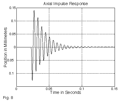
Figure 8 – Axial Impulse Response
Since f0 is proportional to the square root of the stiffness/mass ratio, significant reductions in moving mass, or increases in screw-nut and duplex bearing stiffness, are required to appreciably change the natural frequency. In some cases, such efforts can be counterproductive; switching from the DOVER anti-backlash nut to a stiffer ball nut can increase the natural frequency, but also increase the Q, resulting in a longer overall settling time. The inherent damping of our spring loaded, anti-backlash nut is effective in minimizing settling times. Figure 9a shows the settling performance of a single-axis stage executing a 1 millimeter move. As the graph indicates, moves may require several tens of milliseconds in which to settle to a rest; depending on the size of the target position window, this can take even longer. In the case of small moves (for example, disk drive track-to-track testing), the step excitation is smaller, and the settling time to within a given target window improves commensurately. We have developed extensive models of stepping motor driven stages, and can use these to predict stage performance.
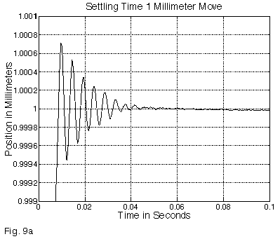
Figure 9a – Settling Time, 1 Millimeter Move
Dynamic performance of a positioning table becomes key when short, high speed moves are performed repetitively, with a brief user function performed at each location. The overall throughput is then closely tied to how much of the cycle must be spent waiting for the stage to settle. Note that in such cases (Figure 9b), a high degree of repeatability can be obtained without waiting for the stage to settle; while not yet in its final location, the stage may be in a highly predictable position at a fixed time interval after the move termination. While useful for brief tasks such as firing a laser, longer tasks (such as a video frame grab, which requires 30 milliseconds) will see a “smeared” stage position. A useful rule of thumb in high repetition rate systems is to compare the natural frequency with the desired repetition rate: expecting a table with a 100 Hz natural frequency to move and “stop” at 10 Hz is achievable (assuming a well damped system); similar operation at 50 Hz is unrealistic. At or above 100 Hz, essentially sinusoidal motion with no discernible pauses will result.
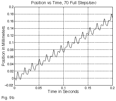
Figure 9b – Position vs. Time, 70 Full Steps/sec
Move and Settle Time Settling Time, Servo-Based Systems Servo systems exhibit a number of dynamic behaviors that differ from those of stepper driven positioners. In most cases, servo controllers execute a PID loop, in which the commanded output is proportional to the error (the P term), the rate of change of the error (the D term), and the errors at previous samples of the system (the I term). A fundamental parameter of any servo loop is the servo bandwidth f0, which is that frequency at which the servo loop’s ability to counteract disturbances begins to roll off. In general, the response curve of a properly tuned (well-damped) servo loop is flat from D.C. out to the servo bandwidth, at which point the system response rolls off as 1/f02. The goal in selecting servo tuning parameters is usually to maximize the servo bandwidth, with the upper bound on the bandwidth usually set by phase lag from the lowest frequency mechanical resonance. Two other fundamental properties, related to the servo bandwidth, are the system natural frequency, w0, which is 2 x š x f0, and the time constant, t0, which is simply the reciprocal of w0. The effect of the proportional term can be thought of as a torsional or axial spring (Figure 10). In this graph, the error, in microns, is plotted against the absolute value of torque or force. In all but air bearing systems, there will be a frictional component present. In systems without an integrator, the proportional term can only correct error down to the level at which friction is present; in the graph of Figure 10, the system would be left with a following error of 5 counts. The function of an integrator is to use the memory of the error in previous samples to push the command output above that produced by the proportional term alone. This will result in zero steady state error, but the effective time constant, tint, can be five to ten times the system time constant t. Since torque (or, in a linear motor system, force) is only produced in response to an error, a servo system will always exhibit a lag during acceleration and a lead during deceleration (Figure 11). The servo lead, or inertial following error, which is present at the end of the deceleration phase will equal: 4 x Acc./ w02 (in meters), where w0 is the natural frequency described above. For a given moving mass and servo bandwidth, we can also calculate the servo stiffness, (in Newtons per meter), which is the slope of the V shaped lines in Figure 10; this turns out to be equal to mass x w02/4. The limit (in meters) to the following error that can be corrected by the proportional term can now be calculated – it is simply the friction (in Newtons), divided by the stiffness, (in Newtons per meter). We will refer to this as frictional error.
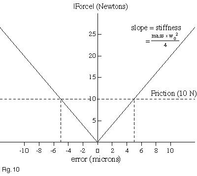
Figure 10 – Force vs. Error
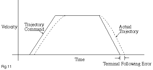
Figure 11 – Servo Lag
We can now examine the settling behavior of the system over time, with the key inputs being the desired settling window, the inertial following error, the frictional error, and the two relevant time constants, t0 and tint. In the absence of friction (the easiest case), the settling time is simply t0 times the natural log of the ratio (inertial following error / desired settling window). Put more simply, the inertial following error will drop by the factor of 1/e (0.36) for every time constant, t0. If the servo bandwidth is 50 Hz, then t0 is 3.2 milliseconds. In a system with an acceleration of 2G (~20 meters/sec2), the inertial following error will equal 811 microns. If our goal is to settle to within 2 microns, the time required will be 3.2 x ln(811/2), or 19.2 milliseconds. The price paid for friction will now become apparent. The servo stiffness of this system, if the mass is 10 kg, will be 246,500 N/m. With a friction of 10 Newtons, the frictional following error will be 41 microns. The settling behavior now consists of two phases; in the proportional phase, which settles to 41 microns at t0, the time required is 3.2 x ln(811/41), or 9.6 milliseconds. In the integrator phase, however, the time constant is 5-10 x longer, and the system settles from 41 microns to 2 microns at the considerably slower tint, for a settling time in this last phase of ~20 x ln(41/2), or 60 milliseconds. The overall settling time is then ~ 70 milliseconds, compared to ~10 in the absence of friction (Figure 12). The above examples assume that no acceleration feed-forward is employed; this has the benefit of reducing (in some cases significantly) the inertial following error, and hence reducing settling times. Figures 13a and 13b show the effect of acceleration feed forward in reducing the overshoot (and hence improving the settling time) in a high acceleration (2G) move. Also assumed in the example above were a sufficiently fine encoder resolution, and the absence of external perturbing forces or, vibration.
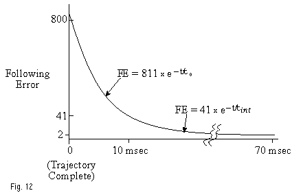
Figure 12 – Settling Time
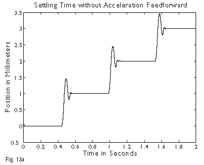
Figure 13a – Settling Time without Acceleration Feedforward
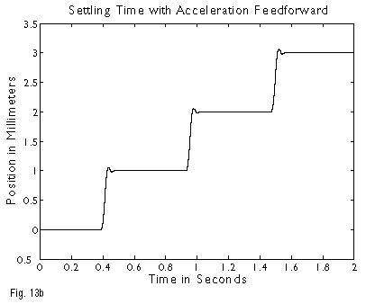
Figure 13b – Settling Time with Acceleration Feedforward
While all servo positioning systems share the basic properties previously described, specific variants require additional scrutiny. For the sake of simplicity, the previous section was tailored to linear motor servo systems. In leadscrew driven systems, the payload mass is seen as a reflected inertia, scaled down by the square of the lead. The leadscrew itself often dominates the system inertia, and the motor inertia and coupling stiffness must also be considered. Rotary encoded servo stages share some attributes with the stepping motor driven stages discussed previously. There is still a strong component of the settling behavior which is simply the axial spring-mass resonance, and the ringing due to this is largely ignored by the servo loop. It consequently damps out by purely mechanical means. A linearly encoded, leadscrew based servo stage shares some attributes with both its rotary counterpart, and linear motor systems. Leadscrew inaccuracy is no longer an issue, but the axial resonance is now directly part of the position servo loop. While it is typically higher in frequency than the servo bandwidth, it contributes phase shift at the lower frequencies that can affect loop stability. This has the effect of reducing the achievable servo bandwidth, so it is valuable (as always) to explore design changes that will raise the frequency of the axial resonance. In some cases, a “dual loop” architecture may prove useful; in this case, the derivative term is provided by a tightly coupled, motor mounted rotary encoder, with the linear encoder used only for position feedback. Another useful stratagem is to employ notch filters, implemented in either the analog signal path or in digital domain, to lower the gain of the servo loop at the axial resonance and hence allow the servo bandwidth to be increased. Servo systems based on linear motors have some similarities with linearly encoded leadscrew-based systems, with the distinct advantage that there is no leadscrew. The elimination of this high-Q mechanical resonance, with its unwelcome phase shift, allows the servo bandwidth to be increased significantly. The limit to the achievable servo bandwidth in linear motor systems arises from phase shift due to the inevitable presence of structural resonances, as well as the zero order hold resulting from the discretely sampled digital loop filter. When analyzing position servo systems, it is customary to close a weak position loop, and inject a swept sine wave to detect the various system resonances. The design can then be re-evaluated, with an eye towards identifying and improving any existing resonances, either by increasing their frequency or lowering their “Q”. Multiple notch filters, of varying attenuation and frequency response, can also be added to allow the bandwidth to be pushed as far as is practical. The simple expedient of acceleration feed-forward can be added to reduce the inertial following error, with a commensurate reduction in the settling time. This term does not affect servo stability, as it is outside of the position loop. Additional feed-forward methods based on convolutional algorithms can further reduce the time needed to settle. High resolution systems often require vibration isolation to minimize the effect of external vibration. Conventional isolation systems employ sluggish pneumatic actuators; when the center of gravity of the stage moves, they introduce a tilt into the stage mounting surface. While leadscrew based systems largely ignore this effect, linear motor stages see a force equal to the moving mass times the sine of the angle. This force acts to induce a following error, and degrade the settling time. Active isolation systems can be effective in addressing this issue. While some of the graphs in this section can serve as rough guidelines, the factors that contribute to move and settle times vary widely with a large number of factors. These factors are driven by both the application requirements, as well as the specifics of the design of the positioning stage, servo loop filter, feed-forward strategy, and external equipment. We have developed relatively sophisticated mathematical models, which allow us to optimize a given system for a specific application and budget.
Motion Control Handbook
Abbé Error
Accuracy in Positioning Systems
Constant Velocity
Cosine Error
Full Coil vs. Half Coil
Glossary of Terms
High Vacuum Positioning Tables
Interferometer Feedback Systems
Interpolated Motion
Lead Screws and Ball Screws
Linear Motors
Limit Sensors
Limitations of Piezos
Low Magnetic Field Tables
Linear Positioning Accuracy
Mapping
Microstepping
Midrange Resonance
Motion Calculations
Mounting Issues
Move and Settle Time
Positioning Systems Overview
Repeatability
Resolution
Rotary Motor Mount
Servo Motors
Slow Down to Speed Up
Stepper Motor
Thermal Expansion
Torque and Force Requirements
Units of Measure
Vibration Isolation Systems
