Stepper Motors
Standard 1.8 degree stepping motors (Figure 27) consist of a laminated, toothed stator wound with two center tapped coils, surrounding a 50 pole hybrid rotor. The rotor consists of an axially magnetized permanent magnet, with two laminated iron cups. Unlike DC motors, applying current to the motor windings generates a torque which resists rotation (the holding torque).
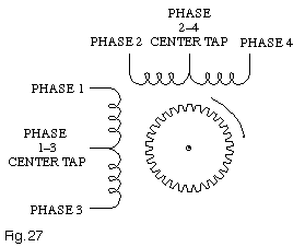
Figure 27 – 1.8° Stepper Motor
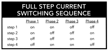
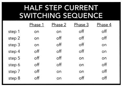
However, by switching coils on and off in a specific four step sequence, (Figure 28a), the rotor will “step” 1.8 degrees per current change. An optional eight step sequence, (Figure 28b), doubles the resolution to 0.9 degrees (400 steps per revolution). Rotation is therefore achieved by simply applying an appropriate sequence of winding currents.
Several factors complicate this otherwise simple scheme. An energized stepper motor exhibits a rotary stiffness which resists deflection from its current position. Coupled with the rotary inertia of the rotor, this spring-mass system produces a fundamental resonance in the 50 to 150 Hz range. Operation at step rates near this natural frequency increases noise and vibration, and may cause the motor to drop out of synchronization (lose position). The use of microstepping, which is implemented on all DOVER stepper motor drives, dramatically reduces or eliminates this effect.
Due to the motor rotor inertia, there is a limit to the step rate that can be applied to a stationary motor without it stalling, or failing to follow the step train. This rate, called the STOP-START RATE, is a function of the motor’s holding torque, rotor inertia, and load inertia. It ranges from 400 to 1000 full steps per second (2 to 5 revolutions per second); a typical value for a lightly loaded 23 frame motor is 700 full steps per second. To operate at step rates above this value, the step frequency must be accelerated, or “ramped” from a rate below the start-stop rate to the desired top speed. The starting frequency is usually chosen to be above the fundamental resonance and safely below the stop-start rate; a value of 400 full steps per second (2 revolutions per second) is typically employed with 23 frame motors.
In addition to resisting instantaneous starts at high step rates, the rotor (and load) inertia can produce overshoot if the pulse train is abruptly terminated. Accordingly, the stopping point must be anticipated and the motor ramped down to an appropriate frequency (again, 400 full steps/second is typical) before stopping. The overall velocity profile for a move is shown in Figure 29a; short moves, which may not reach the programmed top speed, result in triangular moves, as shown in Figure 29b. The allowable acceleration and deceleration values are determined by the motor’s torque, drive type, and the total inertia (see Torque and Force Requirements).
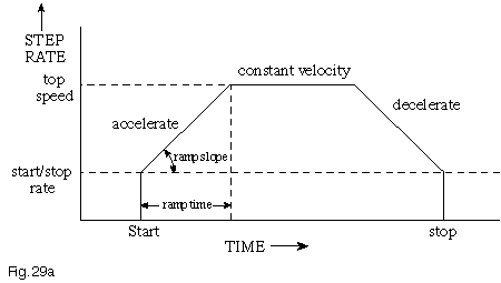
Figure 29a – Trapezoidal Velocity Profile
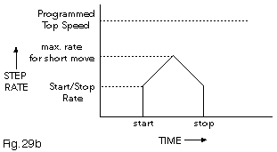
Figure 29b – Triangular Velocity Profile
Having implemented appropriate start-stop rates and acceleration/deceleration ramps, the next concern is usually the maximum achievable slew rate. This is dominated by the inductance of the stepping motor’s windings. As a result of this inductance, the current in the motor windings does not instantly rise to its expected value of V/R. Instead, it follows the formula:
I= V/R x (1-e-R/(Lt))
which starts out linearly and then asymptotically approaches the level expected from the winding resistance and the applied voltage. At low step rates, (Figure 30a) the winding current has sufficient time to reach its full value, providing rated torque. As the step rate is increased, however, the winding current can only build to a fraction of its full torque value before it is switched off (Figure 30b). As a result, motor torque falls with increasing step frequency; eventually, there is insufficient torque to drive the load and the motor stalls. Speed-torque curves (Figure 31) can be broken into two regions; a low speed region within which torque is constant, and a high speed region, within which torque is inversely proportional to frequency.
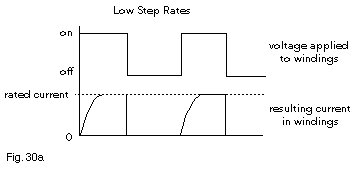
Figure 30a – Low Step Rates
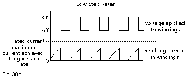
Figure 30b – High Step Rates
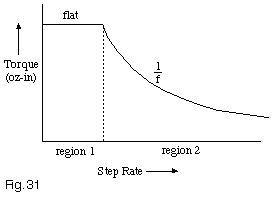
Figure 31 – Speed-Torque Curve
The challenge in driving stepping motors is to get the current to rise as quickly as possible, thereby providing more high speed torque. One technique, called unipolar L/R, sends current into the center tap of each coil, and alternately switches one end of each winding to ground (Figure 32a). The unipolar L/R drive gets around the slow current built-up by operating the motor from a voltage many times higher than its rating. Large dropping resistors are used to limit the motor current to its rated value. The effect of the added resistors is to make the load more resistive and less inductive in nature (changing the L/R term in the equation), which causes the current to build up quickly. This technique is limited in practice by the resulting large power dissipation in the dropping resistors, and has been superseded by chopping drives (see below).
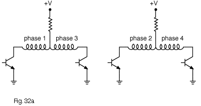
Figure 32a – L/R Drive
A more advanced technique, referred to as a bipolar chopper, uses twice as many transistors in an H bridge configuration (Figure 32b). By turning on diagonally opposed transistors, current can be made to flow in both directions through the coil. Generally, only half of each coil (center tap to one end) is driven; refer to “Full Coil vs. Half Coil“. To produce the fastest possible rise of current in the winding, the drive voltage is set at 10-20 times the rated coil voltage. A sensing resistor is then used to shut off current to the motor when the rate current is reached. Current then recirculates through the winding until it decays below the sensing threshold, when the transistors are again turned on. The motor current is therefore “chopped”, typically at an inaudible 20 KHz, providing optimum high speed performance without exceeding rated motor current. All DOVER stepping motor drives employ bipolar choppers, as well as microstepping; we also offer the drive modules separately (MDM7 and HRDM20), for OEM users interested in incorporating them into their own systems. All DOVER chopper drives incorporate full protection from midrange instability, an otherwise potentially serious stepping motor resonance (see Midrange Resonance).
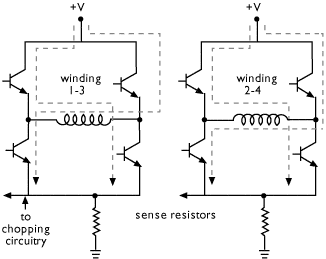
Figure 32b – H-Bridge Chopper Drive
When operated for optimum performance, stepping motors should be expected to run hot. While it may seem alarming to first-time users, case temperatures of 100 – 150 degrees F are of no concern, given the 125 degree C (257 degree F) rating of the motor coils. A cool or luke-warm motor is, in fact, operating at below peak performance. Some controls (the DOVER 100 and 300 Series, for example) incorporate automatic logic to reduce current and hence heating, when not moving. Another common concern regards the “stalling” of stepping motors. While highly undesirable in any given application, stalling will not, even if prolonged, result in damage to the motor or drive.
Motion Control Handbook
Abbé Error
Accuracy in Positioning Systems
Constant Velocity
Cosine Error
Full Coil vs. Half Coil
Glossary of Terms
High Vacuum Positioning Tables
Interferometer Feedback Systems
Interpolated Motion
Lead Screws and Ball Screws
Linear Motors
Limit Sensors
Limitations of Piezos
Low Magnetic Field Tables
Linear Positioning Accuracy
Mapping
Microstepping
Midrange Resonance
Motion Calculations
Mounting Issues
Move and Settle Time
Positioning Systems Overview
Repeatability
Resolution
Rotary Motor Mount
Servo Motors
Slow Down to Speed Up
Stepper Motor
Thermal Expansion
Torque and Force Requirements
Units of Measure
Vibration Isolation Systems

