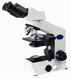
Automated Digital Microscopy and Fluorescence Imaging
Modern biomedical, life science and diagnostic instruments rely on automated digital microscope technologies. DNA sequencers, cell imaging instruments, and digital pathology scanners are just a few of the many applications for digital microscopy solutions. When designing these complex systems, there are a lot of options to consider which involve tradeoffs in performance, throughput, and cost.
In this video, we will explain some of these options at a very basic level. We will explain the XY stage for sample positioning, and high-precision microscope stage objective focusing motion. Since many life science and diagnostic applications require fluorescence imaging, we will cover the basic concepts and components that make fluorescence work.
In modern microscopy systems, the eyepiece has been replaced with imaging sensors which receive inputs through a microscope objective, a complex lens. We will shed light on objectives and compare finite conjugate objectives and infinity corrected objectives to help you select the right type for your needs. If your instrument involves fluorescence imaging or a laser autofocus system, for example, you will need a fluorescent filter cube in addition to an objective to get the desired image at the imaging sensor.
Lenses date back to about the 13th century and they were used, at that time, for both making things bigger and for correcting vision issues. It wasn’t until another 400 years, in 1595, that the compound microscope was invented. There is some dispute as to who actually invented it, but fortunately they’re both named Hans.
Compound Microscopes
The compound microscope consists of a sample and an objective lens which is spaced a little more than one focal length away from the sample. This creates an image at a further distance away. The key innovation was to add the eyepiece lens, which allowed a human eyeball to view the image at high magnification. Which itself was high magnification from the sample.
For most of the 400 years since their invention, compound microscopes were all manual. The sample XY motion is manual, by the human operator. The Z focus motion is manual, again by the human operator, and the imaging is done with originally one, and then later two eyes. And it was all human interpretation.
These days, automated digital microscopes, are at the heart of a vast array of modern biomedical, life science, and diagnostic instruments from pathology scanners to DNA sequencers to cell imagers.
How does a digital microscope work?
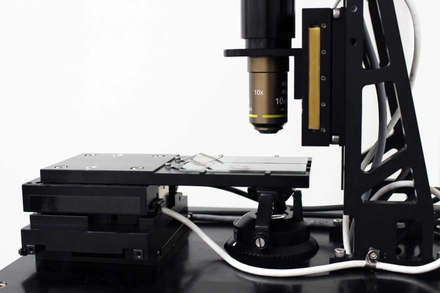
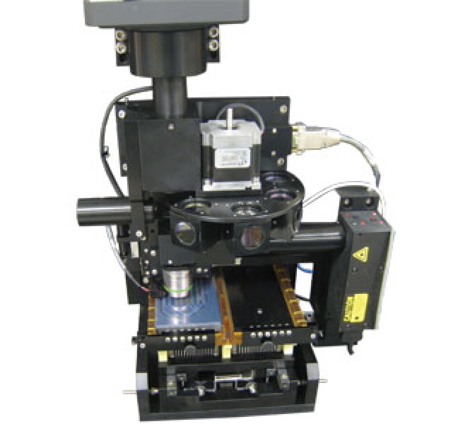
This Microscope XYZ with slide shows an automated digital microscope which consists of a programmable high precision XY stage and our DOF-5 Z objective focusing stage. This system does automated focusing, automated XY motion, and has a CCD camera replacing the human eye. The field of view of a microscope is typically very small. It can be a fraction of a millimeter to perhaps two millimeters, and, the sample is much larger. For example, the microscope in the image is holding 2 slides which are each 25 by 75 mm and are dramatically larger than the field of view. To overcome that, an automated microscope will take many pictures of the sample across the X and Y space of the slide.
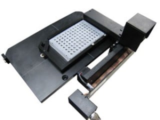
There are also larger sample formats, this image shows an automated XY stage with a 96 well microtiter plate, in this case, a 96 well. There are also 384 and 1536 well microtiter plates. This is a very large item, so if we’re going to image much of it, we have to move perhaps a millimeter at a time, take a picture and move on to image the entire sample.

A third example of a large sample is a flow cell. The flow cell shown is used in DNA sequencing. Reagents enter and leave the lanes, and there are 2,000 images in each lane. Since there are eight lanes, this adds up to 16,000 images in this one flow cell!
What was just described is referred to as sequential field imaging. Take a picture, move and stop, and take another picture. Repeat this sequence over and over until the total area of interest has been covered. There’s another mode called TDI constant velocity scanning imaging and in this case, as you go along the long axis of your sample, you move at a constant velocity. You’ll then step over and do another swath. The position, typically through linear encoder feedback, is used to trigger vertical transfers in a CCD camera to perfectly coordinate the imaging sensor with the motion.
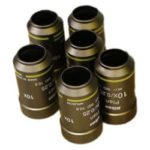
Now, it’s important to point out that, the compound, the eyepiece obviously is not present in a digital imaging system. In this case, an eyepiece is replaced with an imaging sensor and the light from the sample goes up directly to the imager with only a single lens. It’s usually a fairly complex lens and it’s referred to as an objective. Here are some objectives.
What does the objective lens do on a microscope?
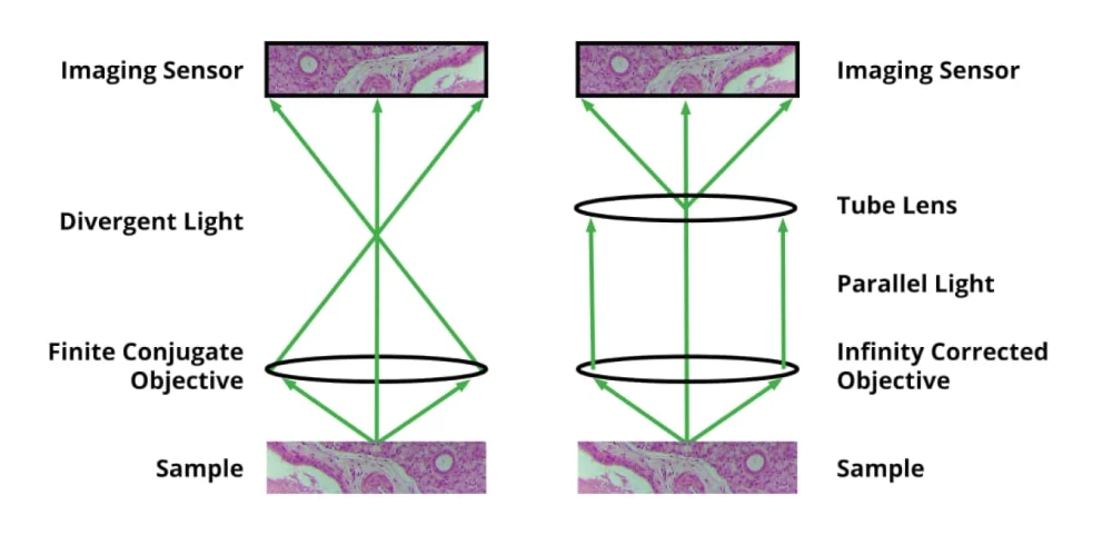
It’s important to point out that there are two basic types of objective. The first is a finite conjugate and the objective images the sample onto the sensor plane, but there’s a bit of an issue with this because you may want to introduce additional optical elements above the objective. With a finite conjugate objective, the light is diverging and that makes adding optical elements a little challenging. So, in addition to a more traditional finite conjugate objective, there is the infinity-corrected objective. In the case of an infinity-corrected objective, the light coming out of from any given point on the sample is parallel. Using an infinity-corrected objective will require one additional optical element which is called a tube lens. It is placed between the objective and sensor, and it takes the parallel light from the objective and produces the image for the sensor. The advantage of an infinity-corrected system is that you get to put additional optical elements in this area and with parallel light, they don’t produce the aberrations that would otherwise be the case with angled light from a finite conjugate objective.
For help with critical optical calculations for choosing imaging sensor and objective:
One of the optical systems that you might want to introduce into that infinity path is a laser autofocus system. A beam splitter is placed in the parallel path and would reflect the 780 or 890 nanometer wavelength of the laser autofocus. That would go through the objective, focus onto the sample reflect back up and come back to the autofocus system. The beam splitter is a wavelength sensitive device so it does not allow any of that laser light to reach the camera but it does allow continuous feedback of the sample position to automatically adjust z position and remain in focus at all times. The signal from the autofocus to Z stage is analog or digital step and direction. Dover Motion’s DOF-5 objective focusing stage accepts step and direction to allow continuous high bandwidth focusing irrespective of sample motion or how flat the sample is.
How does a fluorescence microscope work?
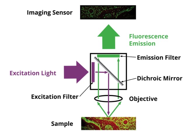
Another common optical element that can be introduced in the infinity objective parallel light path is a fluorescent filter cube. It consists of a beam splitter, an excitation filter, and an emission (fluorescence) filter. Light comes in through the excitation filter and is sent to the sample, the sample in many cases will fluoresce because it has been labeled or stained with fluorophores and a specific wavelength of light will come out of the sample. That light transmits through the beam splitter and through the emission filter which only allows specific wavelengths of light to pass through. Fluorescence imaging is very valuable in both DNA sequencing and diagnostic imaging applications.
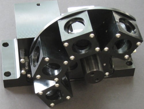
With a single fluorescent filter cube, you can see the presence or absence of a single fluorophore in the sample, but in many cases, you want to have a number of fluorescent probes. For example, in DNA sequencing you’ll want to have four for A, G, C, and T. This is an example of a 4 channel fluorescent filter cube assembly where a rotary stepper motor indexing each filter cube into the optical path one at a time. Another option is to use a linear stage with the filter cubes mounted in a straight line.
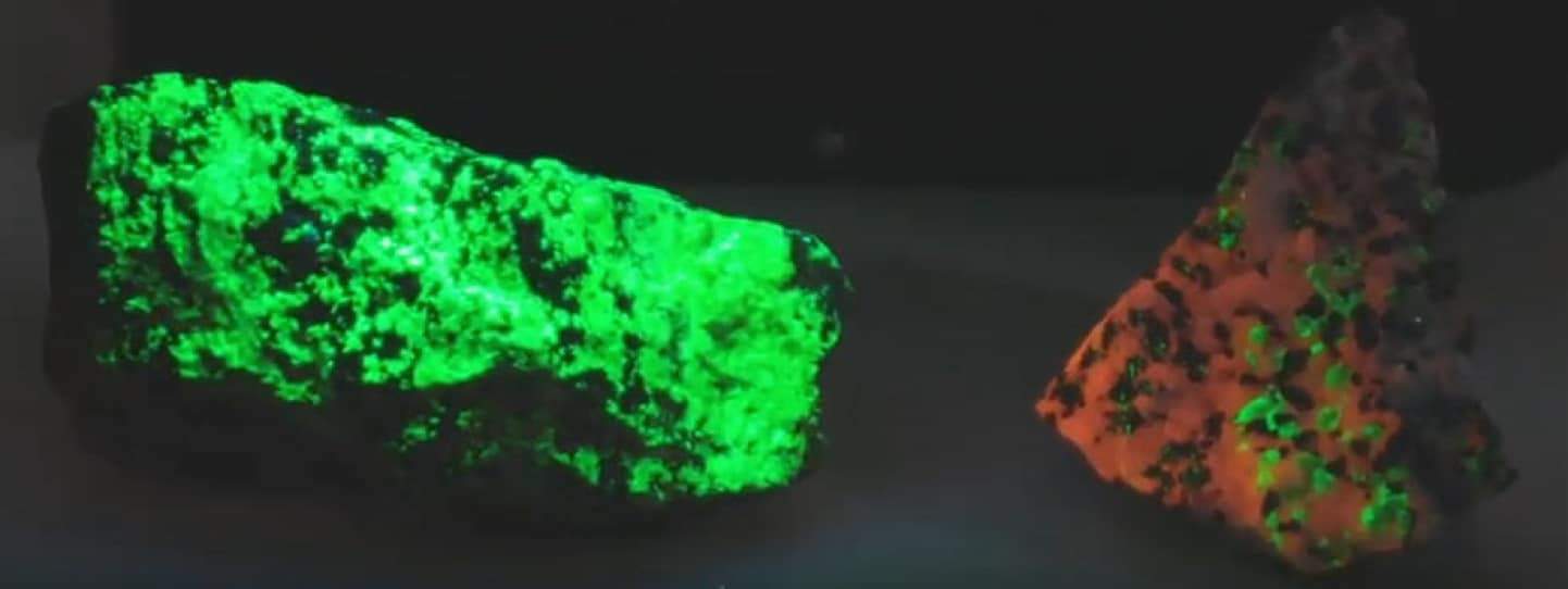
Some minerals which when excited with ultraviolet light, will fluoresce red and green in the visible. An example of this is shown in the image here, green willemite and red calcite with some green willemite. The excitation light is high energy, ultraviolet with a wavelength of 257 nanometers. It hits the atoms, their electrons are excited to a higher energy state and then when they decay back down they don’t make the jump all at once, they emit light but they emit light that is redder. In this case, redder than ultraviolet, which is green and red.

