Pinouts - Standard Products
SmartStage™ XY Pinouts
DOF-5 – Objective Focusing Stage Pinouts
Linear Motor Stage Pinouts
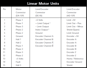
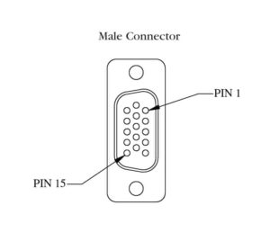
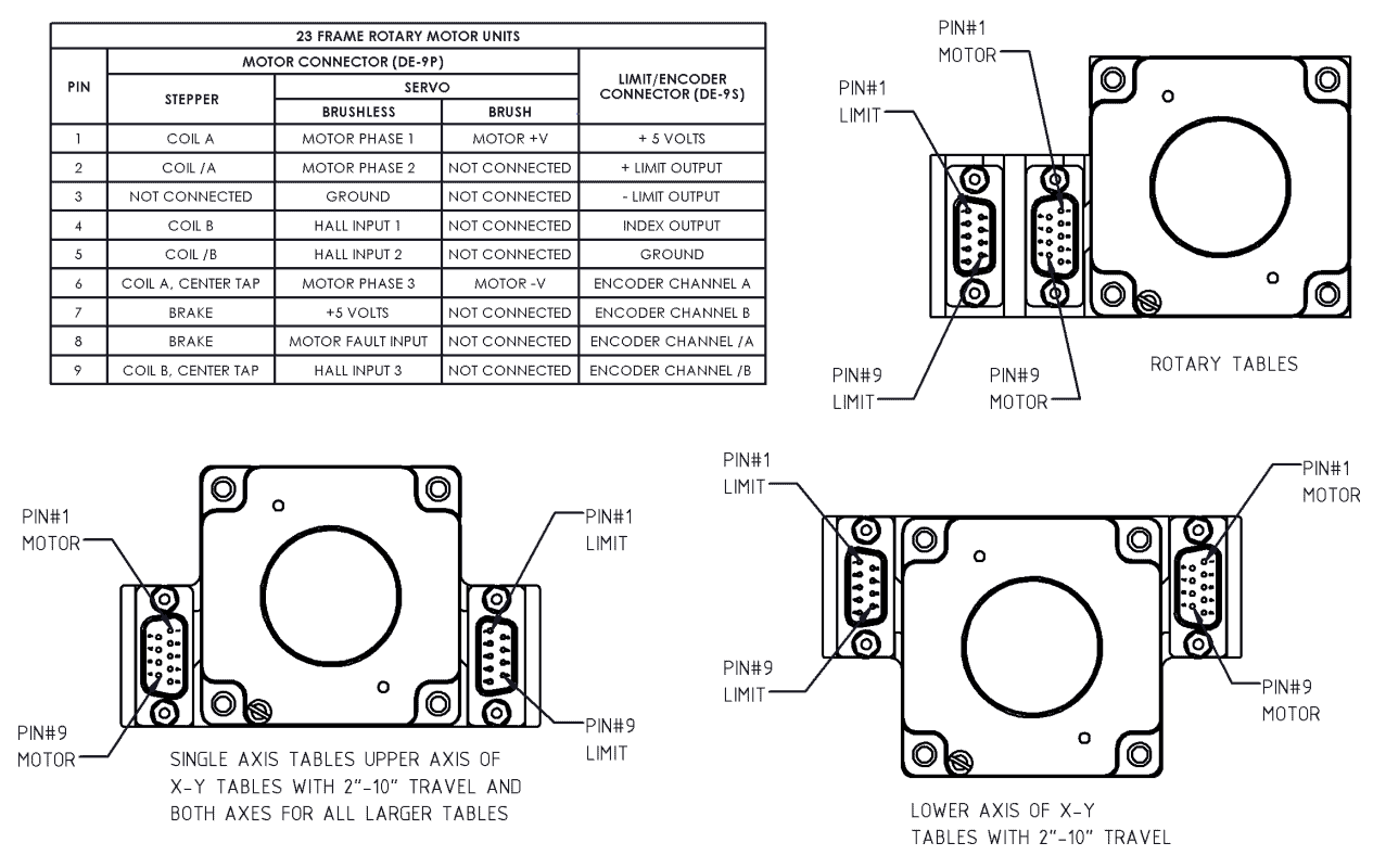
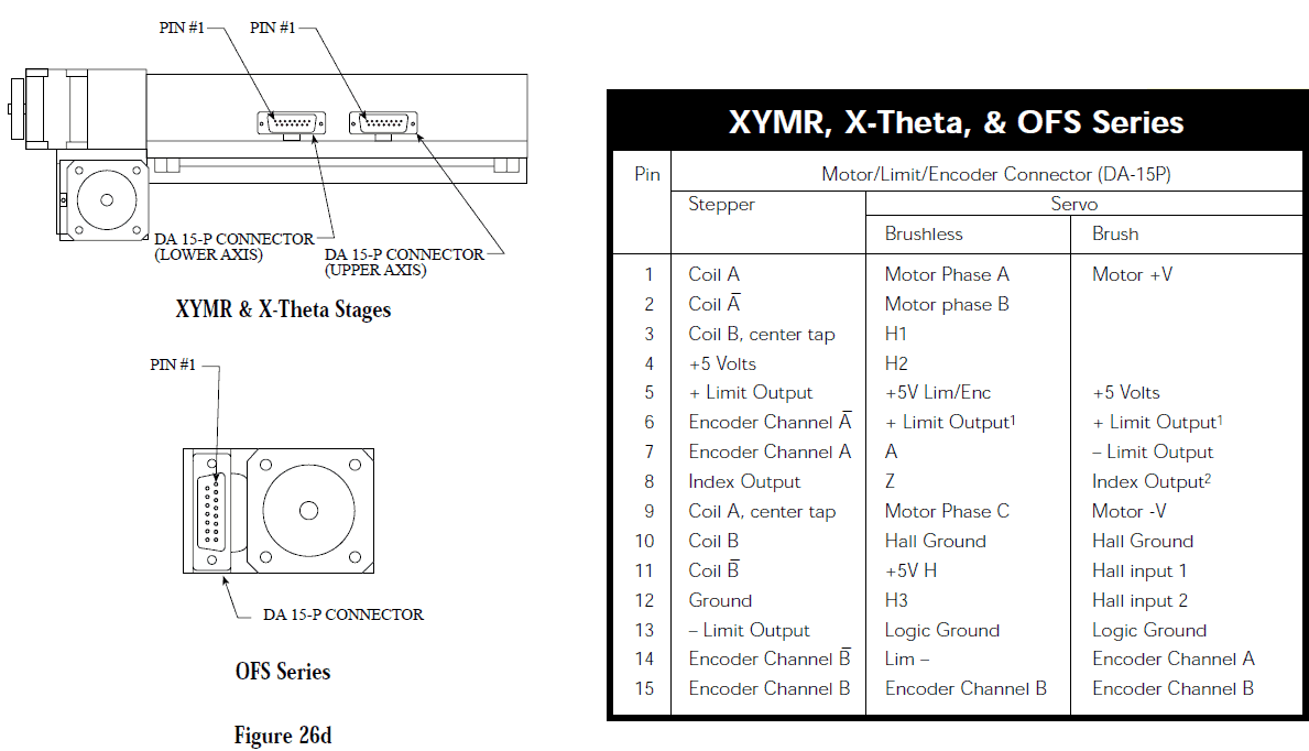
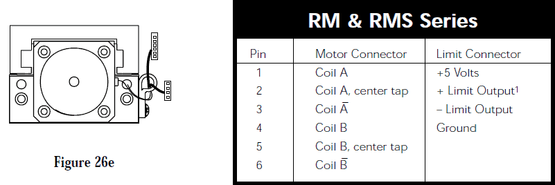
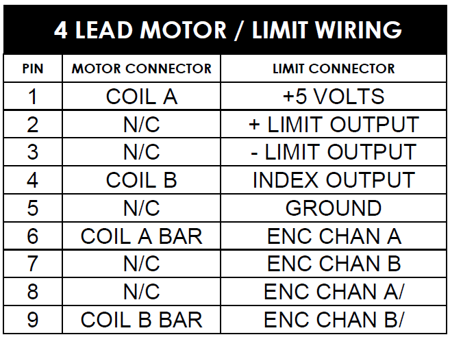
The following pinouts detail the assignment of motor and limit/encoder connector pins. Note that where applicable, two connectors are used; they are opposite polarity, so that their pin numberings are mirror images of each other. Refer to the tables and figures (26a-e) below for details.
Our linear motor driven units utilize a DA-15P connector for the motor signals and a DE-9S connector for the limit and encoder signals of each axis. This includes our SAS™, Impulse™, and AirBeam™ products.
Products utilizing a 23 frame rotary motor include a DE-9P connector for each motor and a DE-9S for the limits/encoder for each axis. If using a linear encoder option, see HD-15P limit/encoder connector column in the Linear Motor Units chart above. Note that the motor mount is inverted on the lower axis of monolithic X-Y tables (2” to 10” travel). The following pinouts apply to our XY, XYR, XYL, OFL, TM, TMS, LM, FM, XM, HM, HMS, Z-Elevator, Z-Theta, RT, and RTR Series units.
Our XYMR, X-Theta, and OFS Series units use a single DA-15P connector for each axis.
Our RM and RMS Series units utilize latching in-line connectors.
Products utilizing a 17-frame rotary motor with 4 leads include a DE-9P connector for each motor and a DE-9S for the limits/encoder for each axis. The following pinouts apply to our KV, URS and custom stages.

