Z Focusing
Z Focusing
In most imaging applications, the distance between the optics and the sample must be adjustable to ensure that the image can be brought into perfect focus. This is generally performed via a Z-axis focusing stage in which either the sample or the optics are moved along the optical axis. The range of required motion varies depending on the application, the sample, and the optics. Examples that can require additional focus travel include:
- Multiple sample types (e.g., microscope slides, as well as microtiter plates)
- Non-parfocal objectives, each with a different focus spacing
- Non-planar or thick samples (e.g., tissue samples or cultured cells)
- A need to retract the optics during a load/unload operation

The Shortcomings of Piezo Technology
Z autofocusing stages are often associated with piezo driven products, but the restricted travel of piezo systems (typically 100 to 300 microns) often leads to compromises in system performance. All three constituent components of a piezo system—piezo linear actuators, piezo flexures, and piezo cap gauges—are intrinsically limited in travel. Attempts to extend the travel, such as employing lever amplification, dramatically decrease the focus stage’s resonant frequency and stiffness. Moreover, piezo system controllers are specialized and costly.
Direct Drive Z Stages
Dover Motion has been building high performance, direct drive Z stages for many years with thousands of systems in the field, many of which operate around the clock. Our strongly preferred focus stage technology uses Lorentz force (linear motor) actuators, together with crossed roller guideways, and optical linear encoder feedback.
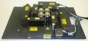
Figure 2: A high-throughput, four-objective optical assembly, each with a magnification of 20X and a Numerical Aperture (NA) objective of 0.80, and independently focused at 1.22 nanometers resolution via continuous laser autofocus.
Compact stages based on these technologies are available off the shelf (see Figure 1), while custom versions can be designed to fit into very constrained spaces (see Figure 2). We also offer compact, cost-effective servo controller modules that maximize the performance of our direct drive focusing stages. The Dover Objective Focuser (DOF) Product offers:
- Travel of > 5mm
- Integrated optical linear encoder with 1.25 nm or 5 nm resolution
- Internal, high performance servo drive and control
- Banking edges for quick, accurate, and repeatable alignment of the motion and optical axes
For applications with more travel or higher payloads than the DOF product offers, we recommend using the Dover MMX™ product family:
- Travels of 25, 50, 100, and 150 millimeters
- Exceptional performance with a resolution of 1.22 nanometers
- A closed loop position stability of around 5 nanometers
The Importance of Depth of Field in Z Focusing
Depth of field is a key parameter in any Z focusing imaging system. It is the region above and below the plane of perfect focus for which the image will not be noticeably degraded. The depth of field for any optical system is a function of the wavelength of the illumination and the NA of the objective. For simple, low-magnification/low-NA systems, such as a magnification of 4X and a 0.15 NA objective in yellow light, the depth of field is generous at about 22 microns. At the other extreme, a 100X, 1.47 NA oil-immersion objective in blue light has a far tighter depth of field of around 70 nanometers. A table of typical objectives and depths of field for yellow light is shown in Figure 4.


In many imaging applications, the optical axis is vertical and the stage moves along the Z axis. We regularly design magnetic counterbalances to assure that projects with larger payloads are properly supported, and to assure a “float upwards” response to a loss of power. An example of this is the MMX™ stage with a magnetic counterbalance that is shown in Figure 5. Another advantage of magnetic counterbalances is that motor heating in vertically oriented applications is reduced to essentially zero.
Different Levels of Focusing Performance
Several advanced microscopy methods can require focus control more stringent than the above depth of field calculations would suggest. These include:
- Confocal microscopy
- TIRF
- Light sheet and structured illumination
- Various hyper-resolution techniques

In such applications, a succession of images may be acquired with each being separated by a small increment along the Z axis, allowing three-dimensional images of the sample to be constructed. Our direct drive focus stage technology is up to the challenge with a servo position stability of around 5 nanometers. Not every application requires the very high performance of our direct drive focus stages. For example, in systems with lower NA objectives the required Z axis precision is greatly relaxed. Furthermore, many applications have lower throughput requirements, which allows slower move and settle times. For these systems we offer lower-cost focus stages that are typically based on fine-pitch lead screws or cams, and open-loop stepping motors. Integration of the fine-pitch lead screw and the stepping motor rotor provides an especially compact and cost-effective focusing actuator. Our application engineers can work with you to find the optimal match to the requirements of your particular imaging system.
Choosing the Right Z Autofocusing Stage
A Z focus stage and its motion controller need additional information to know precisely where critical focus lies. The two most common methods utilize either software or optically based focusing. In software-based focusing, the image from the camera is analyzed as the Z focus axis steps through focus and the images are put through a high-pass filter that derives a value for fine-scale contrast in order to focus. While the incremental cost of software-mediated focusing is very low, as is its speed, making it unsuitable for high-throughput applications. Optical-based autofocusing, on the other hand, relies on sending a laser diode beam down through the objective where it reflects off the sample or a nearby glass surface. This continuous tracking laser autofocus method provides the highest performance, but can be considerably more expensive to implement.
Building the Right Solution for Your Application
Dover Motion offers a variety of standard products for your Z focus needs, and we also specialize in collaborating with our clients to configure the right motion solution for their unique application. With more than 50 years of experience in the life sciences, diagnostics, and factory automation industries, we understand your needs and industry and can provide you the flexibility you need to hit your cost and schedule targets. Learn more about how we can help you with your next project.
Related Products
Z Focusing Products
Automated Imaging Case Studies

The DOF™ microscope stage is optimized for objective focusing with increased travel, higher bandwidth, and lower cost than piezo stages.
| wdt_ID | Travel | 5-9 mm |
|---|---|---|
| 1 | Resolution | 1.25 nm |
| 2 | Repeatability | < 50 nm |
| 3 | Bandwidth | > 225 Hz |

The award winning SmartStage™ XY stage offers high precision and includes an embedded controller inside the stage.
| wdt_ID | Travel | 50 - 200 mm |
|---|---|---|
| 1 | Accuracy | ≤ 10 μm |
| 2 | Repeatability | 0.8 μm |
| 3 | Payload | 10 kg |
