Positioning Systems Overview
Divide and conquer! To help in understanding positioning systems, it is useful to employ a classically reductionistic approach, breaking such systems down into their constituent assemblies.
We will divide the overall function of positioning systems into the following categories:
- WAYS
- ACTUATORS
- MOTORS
- FEEDBACK DEVICES
- ELECTRONIC DRIVES AND CONTROLS
- PERIPHERAL FUNCTIONS
Starting from the top, let’s take a look at “ways”.
WAYS
Any object possesses six degrees of freedom. It can move in a straight line (translate) along any of three mutually perpendicular axes, typically labeled X, Y, and Z. It can also rotate around each of these axes, resulting in theta-X (roll); theta-Z (yaw) and theta-Y (pitch). The job of a way is to delimit these six degrees of freedom, with one and only one degree of freedom remaining. The success with which a given way functions is directly related to its suppression of all five remaining degrees of freedom. Additional desirable attributes are low and uniform friction, high stiffness, and high load capacity.
For linear single axis translation, motion is conveniently described as proceeding along the X axis. The remaining errors are then Y and Z translation, pitch, roll, and yaw. To help clear the relationship of these errors, “pretend you’re and airplane”. Proceeding along an X axis flight path, Z corresponds to gains or losses in altitude, while a cross-wind will produce Y errors. As you fly, you pitch the nose down (theta-Y). You yaw to the left (theta-Z), and perform (if you dare) a barrel roll (theta-X). Bringing the arms up to wing position and making airplane noises helps clarify the axis relationships, as well as drawing unwanted attention.
With rotary tables, the single axis of definition is usually described as theta-Z (yaw); this presumes a horizontal axis of the rotary platform and a vertical rotational axis. With theta-Z (yaw) defined as the desired degree of freedom, the remaining five unwanted degrees of freedom of a rotary table are: X and Y axis linear translation, collectively referred to as radial motion; Z axis linear translation, also referred to as axial motion; and roll and pitch, also called tilt motion.
A rich variety of way technologies are available to choose from, with specific strengths and weaknesses. We’ll examine a few below:
KINEMATIC
Kinematic designs emphasize the use of carefully selected single point contacts t constrain unwanted degrees of freedom. When properly chosen, such designs constrain one degree of freedom for each point of contact. Accordingly, five points of contact produce a system with one degree of freedom (6-5=1); while a system with six points of contact immobilizes and object. In most cases, kinematic designs require a biasing force (gravity, magnetic, vacuum, or springs) to keep all points in contact; in addition, sliding friction can be replaced wit rolling friction through the use of balls as contact points. While these designs are the “purest” in their adherence to mechanical design principals, the small number of contact points results in a low load bearing capacity. Kinematic way designs stand at one end of a spectrum that extends to area-averaging ways (such a dovetail ways – see below) at the other extreme. It can be helpful to consider the trade-offs that occur as you move along the spectrum from kinematic to “elastic averaging”. Kinematic ways offer the highest possible fidelity in reproducing the intrinsic geometric accuracy of the way surface (typically, composed of flats and/or cylinders). They do so with no possible transmission of strain due, for example, to thermal expansion. Inevitably, however, these ideal attributes are countered by a low natural frequency, low stiffness, and low load capacity.
DOVETAIL
Dovetail slides stand in stark contrast to kinematic designs; as opposed to a few selected contact points, they rely upon massive, large area contact surfaces to provide a high stiffness and load bearing capacity. The way surfaces are typically “scrapped” to achieve high flatness and straightness, and the dovetail secures the moving portion to the way. Dovetail ways are commonly found on machine tools, where their high load capacity is paramount. The sliding motion results in significantly increased friction over rolling element ways. As wear occurs due to the sliding action, most designs include an adjustable way preload, or gib, that allows play to be taken out. Despite the high mass typical of dovetail ways, which are frequently fabricated from cast iron, the stiffness is extremely high, approaching that of the way material itself. This results in a high natural frequency for the way assembly, which is essential to high speed milling operations.
BALL WAYS
Ball slides utilize several aspects of kinematic design, such as the use of point contacts formed via highly accurate hardened balls and rods. They incorporate substantial redundancy, however, with a concomitant increase in load bearing capacity. A perforated retainer holds the balls in position, and the entire ball assembly rolls along the hardened rods at one half the speed and excursion of the moving portion. Each ball contacts a rod at one point; four rods surround the balls, resulting in four points of contact per ball. Ball slides offer very low and uniform friction, moderate load bearing capacity, low cost, and very good suppression of the five remaining degrees of freedom. Preload is achieved via elastic compression of the balls against the hardened rods, or deformation of the slide body. Increasing the preload increases the torsional stiffness, increases the frictional force necessary to move the slide, and decreases the load bearing capacity. Decreasing the preload has opposite effects, eventually producing play between the slide members. When preloaded for zero play, ball slides can translate with frictional forces near 0.1 N, and the use of highly polished rods and ruby balls can achieve consistent 0.05± .02 N frictional forces. The force required to slide (as opposed to normal rolling motion) the retainer and ball complement can serve as a sensitive gauge to the preload level. Ball slides, in common with crossed roller slides (see below) experience a shifting of the center of mass of the moving assembly with respect to the ball cage as the slide translates. This variable torque moment can result in pitch being the dominant angular error, particularly as the payload mass is increased. Also in common with crossed roller slides, the retainer and its ball complement can drift away from its centered position over time. Any full travel move will reset the retainer, although rack and pinion and other designs have been developed to prevent retainer creep from occurring. In the absence of such schemes, a positioning system should be capable of developing sufficient force to slide the retainer if necessary. Due to the local geometry of the contact point (2-D convex ball on 1-D convex rod), contaminants are occluded (pushed aside) rather than crushed, making ball ways preferred for moderately contaminated applications.
CROSSED ROLLER WAYS
 Crossed rollers define a way by fitting cylindrical rollers between hardened “vee” ways. Every other roller is rotated 90 degrees, resulting in a symmetrical load bearing capacity. The line contact resulting from the roller-to-vee fit provides a load bearing capacity of about an order of magnitude above that of ball ways. Roller retention and preloading are similar to those of ball way designs. Crossed roller designs provide moderate and uniform friction, high load bearing capacity, high linear and torsional stiffness, moderate cost, and very good straight line accuracy.
The line contact found in crossed roller slides is less effective at occluding foreign particles than the point contact inherent in ball slides. Accordingly, the latter may be preferred for operation in environments with fine abrasive contaminants (e.g. grinding operations). The rolling friction is also increased relative to that of ball slides, although frictional force fluctuations may be reduced due to the averaging characteristics of line contact.
RECIRCULATING WAYS
One drawback to the ball and crossed-roller way types described above is the overall moving envelope. These ways consist of an equally sized base and top member; the top translates approximately 40% of its length to either side, for a total moving envelope of approximately 1.8 times the length, and approximately 2.25 times the travel. This becomes increasingly bulky as the travel increases, and the cantilevered load presented by the overhung top section produces torsional moments and angular error (typically, pitch).
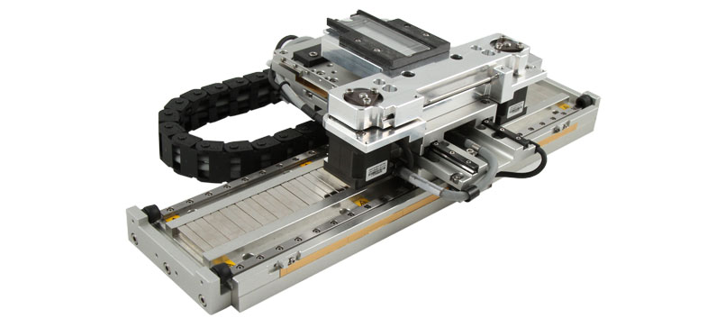
Recirculating way designs consist of a long stationary base, with a smaller shuttle assembly which translates along the base. The overall envelope is simply the travel plus the shuttle length. These designs utilize balls or crossed rollers, much as in way types described in C and D (above), but the rolling elements are deflected off the race and recirculated along a return path to be reused a little further down the way. Our RMS, TMS, and HMS tables are recirculating (“shuttle”) versions of our conventional RM, TM, and HM single axis positioning tables. Recirculating assemblies offer moderate to high load bearing capacity, good straightness, moderate cost, but somewhat uneven frictional characteristics. The latter are due to force fluctuations as balls or rollers enter and exit the preloaded section of the bearing race, and may preclude the use of such ways on systems that require low velocity ripple. Recirculating assemblies eliminate any concern over retainer creep, and can achieve surprisingly high load capacities and stiffness if rollers (as opposed to balls) are the recirculated bearing. An interesting variant in which the rollers are highly elongated “needle” bearings is available, offering the highest load capacity and stiffness. From their invention by Thompson many years ago, recirculating designs have proliferated, with a bewildering assortment of cross-sections and styles. A fundamental distinction can be made among these with respect to preload method; in some designs only a single recirculating race is included, and the uses establishes the preload across two such modules (often widely separated) and two linear guide rails. In other more convenient designs, the preload is factory established internal to each module, which includes two opposing bearing races on a single linear guide rail.
An interesting cross between recirculating and non-recirculating designs also exists; in this case a retainer and captivated ball or roller complement is used which is longer than either the slide base of its top. While no true recirculation takes place, “new” rollers are engaged and “old” rollers leave the preloaded region as the slide translates. Force fluctuations are accordingly still present, and the extra-long retainer complement must be axially constrained and prevented from buckling if creep were to occur.
ROLLER WAYS
Roller, as used in this context, refers to way assemblies which consist of a hardened rail, together with three or more wheel or cam-follower elements which define the orientation and motion of the moving assembly. Examples include square, four-sided ways with six cam followers (a pair on each of two faces, and a spring-loaded follower on each of the two remaining sides), and double vee-shaped ways with three or more mating roller wheels. These designs combine the compact aspect of recirculating assemblies, with very smooth motion due to the absence of recirculating elements. As it happens, the balls or rollers are actually “recirculated”, but remain preloaded at all times in their circular raceways. As a result, friction force fluctuations present in conventional recirculating assemblies are avoided. They are typically low in cost, provide low to moderate load bearing capacity, low and uniform friction, and straight line accuracy as good as that of the way which the rollers follow.
AIR BEARINGS
Virtually frictionless, air bearings consist of a two, three, or four-sided slider, which floats on a thin film of air above a precision ground spar (typically made of aluminum, ceramic, or granite). Because of these features, air bearings provide the ultimate in precision linear motion. Such assemblies provide the highest attainable control over linear and angular errors, achieving linear errors as low as 0.5 microns/200 mm and angular errors of 2-4 arc/seconds/200 mm. All air bearings function by restricting air flow; as a result, a pressure drop occurs across the restriction. As an external load is applied, the gap (typically 5-10 microns) decreases; as the gap decreases, less air flows through the restriction. This decreases the pressure drop across the restrictor, thus increasing the pressure past the restriction. This increased pressure within the gap provides a force opposing the applied load which results in a high load capacity – it’s that simple.
Methods of producing a restriction vary, and include tightly controlled gaps, narrow slots, precision orifices, and porous materials. While popular, orifice designs are prone to single point clogging if any contaminants find their way past or upstream of the filter. Porous designs, often employing carbon or powdered metals, avoid this difficulty and are gaining increased acceptance. All designs must take into account certain hydrodynamic oscillations which can introduce vibration and audible noise.
The trade-offs mentioned earlier between kinematic ways and redundantly constrained ways is repeated with air bearings. The air bearing slider is intended to follow the beam upon which it translates, and it is the accuracy of this beam or spar which controls the overall accuracy. The kinematic version of an air bearing linear way employs five air bearing pads, also called pucks, which support a two sided carriage, or slider. To provide a bias force of these pucks against the spar, vacuum or magnetic preload is employed. The result is the most accurate way of replicating the underlying accuracy of the spar, and the system is immune to translated stress due to lack of parallelism or thermal expansion. Its linear and torsional stiffness are lower, however, and this may result in dynamic linear or angular errors during acceleration or as a result of external forces. The natural frequency is also somewhat lower than ideal. The use of high load capacity pucks, together with fairly high preloading forces and consequently small gaps can improve stiffness and raise natural frequencies.
A Three-sided slider will require a bias or preload force in only one direction, with two opposing air bearings assemblies providing the stiffness in the perpendicular direction. As noted above, this achieves higher stiffness, but air gap variation due to differential thermal expansion between spar and slider must be avoided, and the spar must be very precisely lapped or ground to ensure parallelism. Finally, four-sided designs fully surround the spar and offer the highest potential stiffness.
The linear stiffness of air bearings, typically 50-100 N/m, is well below that found in rolling element steel bearings. Air bearings have vanishingly low friction, provide a compact moving envelope, have good load bearing capacity, and offer superlative straight line accuracy. The latter derives both from their built-in servo control of flying height, and the inherently averaging aspect of air bearing ways. Costs for the air bearing way itself and the necessary support equipment (compressed air, vacuum, filters, regulators, tubing, etc. are higher than those of competing way technologies.
FLEXURES
Flexures are a somewhat neglected way technology. They utilize the bending of flexible members to define a linear translation axis. A common example uses tow thin metal discs with photo-etched spirals connecting the inner and outer diameters. Loud speakers use flexures to define the voice coil motion axis. Parallelogram flexures are another common design implementation. For certain limited travel applications, flexures can be a compact, cost-effective way technology. In addition t a highly uniform motion without rolling artifacts, flexures can function as linear transformers, amplifying or reducing the input movement. A commercially available flexure unit with significant resolution amplification achieves reproducible Angstrom level motion using a simple micrometer head.
ACTUATORS
Having defined a single degree of freedom system through an appropriate choice of ways, we can then address the wholly separate question of how to produce incremental motion along that way. We refer to motion producing devices as actuators. A distinction can be made between actuators that can select one of two positions along a way, and those which can be programmably indexed to any of a potentially large number of positions. Among the former category, the most common devices are solenoids and pneumatic/hydraulic cylinders. In general, if the application requires repetitive positioning at one of only two positions, a “one bit” actuator will usually prove far more cost effective than a full-blown, CPU based smart positioning system. This may, however, result in lower revenues to vendors such as we, who manufacture mere “exotic” positioning systems.
TWO POSITION ACTUATORS
Solenoids
Solenoids are compact, low cost actuators which can, especially if combined with a good way, momentum absorbers, and hardened stops, provide highly repeatable, fast two position indexing. They rely upon the attractive force between a soft iron moving element and the magnetic field gradient produced by a coil. Since it is difficult to produce high field gradients over an appreciable distance, solenoids are usually limited to relatively short strokes (typically, £ 1 cm). Coil heating, A.C. induced vibration or chattering, and a strongly non-linear attractive force are weak points in solenoid based designs.
Cylinders
Pneumatic or hydraulic cylinders provide a low cost, high force, high speed means of two position actuation. While they become increasingly bulky as the travel is increased, “rod-less” variants are available which provide a compact alternative, analogous to recirculating way assemblies. When combined with somewhat complex servo proportional valves and a feedback device cylinders can also be programmably indexed to a large number of positions.
Cams
Cams perform a vast array of two position indexing functions, especially in reciprocating mechanisms. Automotive intake and exhaust valve positioning is perhaps the most familiar application. Despite their use of sliding friction (ostensibly prone to wear), internal combustion engine cam actuations function reliably and accurately, propelling most of us to and from work without incident, despite an average of 1 million operations per day! Cam positioning is generally limited to short travels.
MULTI-POSITION ACTUATORS
Cams
If provided with a programmable rotary actuator, cams can also position payloads at a large number of positions. While the stroke is still limited, a very high resolution can be achieved; with appropriate bias forces, repeatability and stiffness can also be very high.
Piezoelectrics
Piezoelectric elements rely on charge asymmetries in crystal or ceramic materials to produce an expansion or contraction in response to an applied electric field. Such devices can achieve astonishingly high resolutions of as little as 0.1 Angstroms (.0000000004 inches!). In single element form, they require applied voltages of up to a kilovolt, and produce very small travels (less than one micron). “Stacks” of multiple elements can extend this travel range by over an order of magnitude. “Bender” elements can amplify this travel to up to a millimeter (at reduced resolution), and “inch-worm” and resonant devices can in principle attain unlimited travel.
Inch-worms function by integrating three piezo elements (two radial and one axial) along a guide shaft. The elements are sequenced to grab the shaft at the near end, extend the axial element, grab the far end and release the previous radial clamp, retract the axial element, and repeat the process. The axial extension consists of a large number of ~ 4 nm expansions caused by a staircase voltage applied to this element; when the voltage and extension reach their limit, the clamp/unclamp cycle is performed. The devices are delicate, moderate to high in cost, and exhibit some level of artifacts at the clamp/unclamp position period.
Another piezo actuator with unlimited travel is the resonant type. In this design, angled piezo elements oscillate a ceramic gripper along a ceramic spar. The element is driven electrically at its resonant frequency (typically 134 KHz), and each oscillation imparts a small forward or backward motion along the spar. This system can achieve ~ 0.1 micron resolution with speeds of 10 mm/sec. And essentially unlimited travel.
Piezo actuators exhibit non-linearities and hysteresis when operated in open loop mode, and function most effectively when teamed up with a feedback element. The stunning images produced by Scanning Tunneling and Atomic Force Microscopes reveal how high a level of performance can be extracted from these devices.
Tangential
Tangential drive actuators consist of a programmable rotary actuator (motor), coupled to a pair of pulleys connected via a drive belt. The payload, constrained by a separate way assembly, is attached to the drive belt. Such systems are capable of quite high speeds at modest resolutions and forces. Accuracy and repeatability are limited by the belt and pulley quality (unless linear encoders are used). Typical applications include low mass, moderate accuracy payloads which must perform high speed indexing; examples include pen plotters, fluid dispensing, and “pick and place”. With new high strength belt materials, tangential actuators have been expanded recently to support surprisingly high payload masses.
Leadscrews
Leadscrews are by far the most popular actuator for incremental motion systems. They provide a convenient, low cost method of translating the output of common rotary actuators (motors) into linear motion. Leadscrews provide mechanical advantages over tangential drives, with correspondingly higher resolution and force -albeit, with lower speed capability. Conventional leadscrews consisting of solid nuts loosely fit onto a leadscrew offer low cost, low repeatability linear actuation. The simple expedient of designing an anti-backlash leadscrew results in a very high (sub-micron) repeatability system, at low additional cost. In contrast to such “friction” nuts, ballscrews offer (in principle) higher efficiency due to the use of recirculating balls in rolling contact with the screw. While they can offer improved axial stiffness, a compromise between high repeatability and low operating torque often results (especially if wipers are present) in comparable or higher torque levels than in anti-backlash friction nuts. Entrance and exit of balls from the preloaded region can also cause torque fluctuations. Anti-backlash nuts are available with leads from 0.5 mm (.020″) to 2.5 mm (1″), while ballscrew leads range from 2 mm (~ .1″) to 50 mm (~ 2″). While inexpensive rolled ballscrews are regularly introduced claiming performance comparable to that of more expensive, precision ground ballscrews, such claims are rarely met. The decision between ballscrews and anti-backlash friction nuts is often determined by the application; high speed or high axial stiffness favors precision ground ballscrews, while lower speed or high torque uniformity requirements favor anti-backlash friction nuts. Another variation, planetary leadscrews, consist of a number of rotary bearing thread followers arranged in planetary (epicyclical) motion around the leadscrew. In all cases, at least one end of the leadscrew must be fixed (typically via a duplex, angular contact bearing) to prevent axial play. Finally, although unrealized in commercial practice, air bearing nuts present an intriguing possibility.
Linear Motors
Both rotary stepping motors and brush or brushless servo-motors have direct, “unrolled” linear analogies. These provide linear actuation directly, without a mechanical linkage. Both still require a way assembly, although linear steppers often integrate the way into the motor platen. As these devices function as both motor and actuator, they are described in greater detail under Section 3, Motors.
