Interpolated Motion
For many positioning system applications, simple point-to-point moves or constant velocity motion are sufficient. In other applications, more sophisticated movement is required.
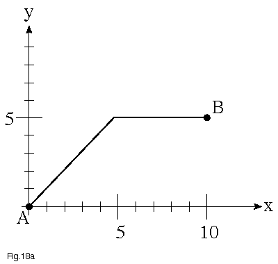
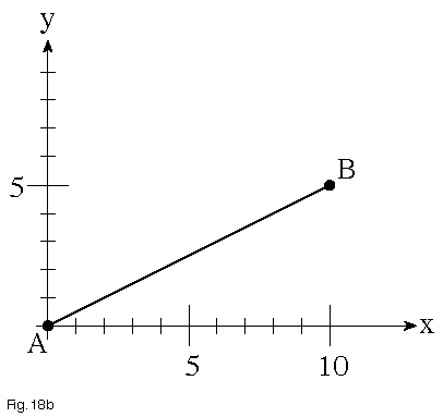
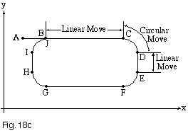
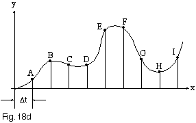
Interpolated motion is called for when the path that an object takes through space is important. For example, when a simple point-to-point system moves two axes at any angle other than 45°, the path will be as shown (Figure 18a), with one axis finishing before the other. One simple improvement that simulates interpolated motion is to very finely set the velocity on each axis, so as to have both axes start and stop at about the same time. More sophisticated motion controllers, which offer linear interpolation, can move at an arbitrary angle, and yet have the point-to-point path be a straight line (Figure 18b). More general examples of interpolated motion include circular interpolation, continuous path motion along arbitrary combinations of linear and arc moves (Figure 18c), and smooth, cubic spline motion through a series of points (Figure 18d).
One common application requires that a third theta axis be maintained tangent to the path, as the X and Y axes follow an arbitrary curved path in the X-Y plane. An example of an interpolated motion system with a tangent theta axis would be guiding a knife through material that is being cut; the blade must always face directly into the motion. Another computational problem we encounter consists of three linear axes with bearings at one end, pushing a planar payload in X, Y, and Theta axes. In this case, retaining a fixed (but virtual) “axis of rotation” as the system moves in the X and Y axes requires extensive trigonometric transforms. A similar case involves the need to perform arbitrary Z axis motion with tip and tilt motions using three linear Z axis stages with gimbals supporting a single payload. Another common problem is to take a Linear – Theta stage and use it to perform X-Y motion. Higher order interpolations, of more limited use, include helical, spherical, and elliptical interpolation.

Figure 18a – Point-to-Point

Figure 18b – Linear Interpolation

Figure 18c – Circular Interpolation

Figure 18d – Cubic Spline Interpolation
Motion Control Handbook
Abbé Error
Accuracy in Positioning Systems
Constant Velocity
Cosine Error
Full Coil vs. Half Coil
Glossary of Terms
High Vacuum Positioning Tables
Interferometer Feedback Systems
Interpolated Motion
Lead Screws and Ball Screws
Linear Motors
Limit Sensors
Limitations of Piezos
Low Magnetic Field Tables
Linear Positioning Accuracy
Mapping
Microstepping
Midrange Resonance
Motion Calculations
Mounting Issues
Move and Settle Time
Positioning Systems Overview
Repeatability
Resolution
Rotary Motor Mount
Servo Motors
Slow Down to Speed Up
Stepper Motor
Thermal Expansion
Torque and Force Requirements
Units of Measure
Vibration Isolation Systems
