Frequently Asked Questions (FAQ)
About Dover Motion
Are you New England Affiliated Technology (NEAT)?
Yes, in 1999 Kollmorgen Corporation agreed to purchase New England Affiliated Technologies (NEAT) of Lawrence, Massachusetts. The business was then moved to Salem, New Hampshire. In 2002, Dover Instrument Corporation of Westborough, Massachusetts was acquired and combined with the NEAT. Today both businesses are under the Dover Motion brand name with onsite design and manufacturing in Boxborough, Massachusetts.
Our Products
Are Dover Motion's products RoHS/REACH compliant?
Dover solders are lead free and our products, components, or systems can be RoHS compliant if required by our clients.
RoHS
The Restriction of Hazardous Substances (RoHS) Directive limits the usage of hazardous materials in the manufacturing of various types of electronic components. The RoHS Directive is enforced in all the European Union Member States and all products must undergo periodic compliance checks.
REACH
The Registration, Evaluation, Authorization and Restriction of Chemicals (REACH) Act is a set of European Union Regulations that address the production and usage of chemical substances in manufacturing. REACH is considered one of the most complex pieces of legislation passed by the European Union and all companies operating within their territory are strongly encouraged to comply.
Do you repair NEAT stages?
Yes, we repair most of the old N.E.A.T product line.
Are Dover controllers LabVIEW compatible?
Yes, our controllers have LabVIEW capability, but we do not support LabVIEW applications unless designed specifically for your project. Please contact us for more information on sample LabVIEW libraries.
What are your control options?
You can view our control options in our product catalog for motion control systems.
How do I ask for a quote on specific product?
Click here to Request a Quote or email us directly at sales@dovermotion.com.
Are Dover products customizable?
At Dover Motion we provide the ultimate engineered motion solutions for our clients. In many cases this involves customizing or configuring our standard products to a client’s unique application and specifications. Please contact us if you’re interested in customizing or configuring one of our standard products, or if you’d like to work with our engineering team to design a unique solution to meet your needs.
Does Dover Motion ship overseas?
Yes, we ship our products internationally and have distributors in designated areas.
Do you have a list of Legacy Products?
We provide various levels of support for our legacy products, some of which are listed below. Please contact us for more information.
- RT™ Rotary Positioner
- Smartstep Microstepping Drive/Controller
- MDM7 & HRDM20 Drive Modules
- 100 Series Stepping Motor Drive
- 700 Series Servo Amplifier
- Airbeam™ Single Axis Shuttle
- The Revolution Spindle™ Air Bearing
- For the new version of the MMG click here.
- The DMM-02XX and DMM-04XX controllers
- NanoSlide -20 Linear Motor Stage
- RM Compact Ball Way Table
- RMS Compact Single Axis Shuttle
- TM Ball Way Table
- TMS Single Axis Shuttle
- XY Ball Way Table
- MAB -100 Linear Motor Stage
- High Speed Linear Actuator – SAS™
- BAZ™ Ultra-stiff Z-Elevator
- Z-Theta™ Z-Elevator with Small Angle Theta
- Micro-Theta-10™ Small Angle Theta with Lockdown
- MicroTheta-5™ Direct Drive Rotary Table
- Platinum-400 Gantry
- Platinum-900 Gantry
- XY Gantry System – SAX
I have an 11-#### part number on my stage, how do I find out what it is?
Please contact our technical support engineers and they can lookup the relevant information for you. Our engineers are available through this link: Technical Support
Technical Questions
Why does my SmartStage or DOF power up with the axis servoing?
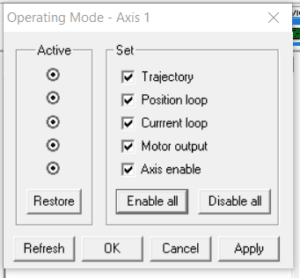
If all items in the Operating Mode window are enabled (per the figure below) when the configuration is saved to NVRAM, then when the stage is power cycled, all items in the Operating mode window will still be enabled, and the stage will be servoing.

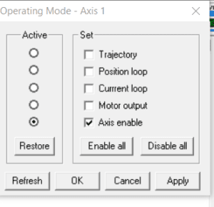
We recommend that you only save the parameters to NVRAM when the “Axis enable” is enabled. All other items should be disabled per the following, prior to saving a configuration to NVRAM:

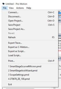
Note that this also applies to saving configurations to files using the Pro-Motion File menu:

Always disable all items in the Operating Mode window prior to saving a configuration to a file.
How fast can the SmartStage L and SmartStage XY products travel?
When the SmartStage L and SmartStage XY products are configured for incremental feedback (GetEncoderSource = 0), then the maximum speed the stage can travel is 150 mm/second. This is a limitation of the feedback source. If this velocity is exceeded, the commutation initialization is no longer valid, and commutation must be reinitialized.
What is a gantry stage?
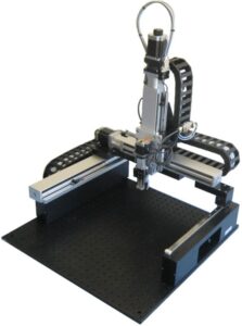
Dover gantry stages are designed to provide unsurpassed repeatability and excellent throughput under real world operating conditions. Our gantry stages are designed to move such items as inspection cameras, laser heads, or specific customer tooling over either removable substrates or fixtures mounted to the base of the system. The gantry base can be provided with mounting holes for interfacing a customer’s hardware to the stage. Due to its simplicity and ease of assembly, it is the ideal gantry stage configuration for OEMs and system integrators building machines for demanding applications. Many of Dover Motion’s standard screw driven and servo motor linear products can be integrated together as a gantry stage to achieve an application’s required accuracy and travel for XYZ motion.
- Pre-formatted base for ease of integration
- Risers to provide space between the base and moving beam
- Integrated cable tracks and hi flex cable
- All axes tested together and burned in to ensure performance and reliability requirements are met before shipment

The example shown above is run by stepper motors and controlled by the Dover Motion multi-axis stepper controller. Incorporating linear encoder feedback and cabling, it achieves 15 to 300 millimeters of XYZ linear motion travel.
Popular applications for gantry stages include:
- 3D metrology
- Inspection
- Probing
- Pick and place
- Laser machining
- Laser scribing and marking
Dover controllers and external cabling are available to create a complete turn-key motion system for gantries. Our controllers have coordinated motion capabilities for accurate multi-axis lines, arcs, and circles. Optional rotary or linear encoders are available to improve accuracy and repeatability. For the most accurate positioning requirements, two-point and multi-point compensation can be programmed for each axis. Dover Motion’s control options include an intuitive user interface and three-axis joysticks are available for control of the XYZ axes.
Can you tell me what pitch lead screw I have in my stage?
Unfortunately, this varies by customer. If you are requesting any specific information on your stage or system, please have the serial number available when you call or email. Examples could be lead screw pitch, stage travel, limit type, and stepper or servo motor.
Are your standard limit switches typically open or closed?
Our standard switches are typically open.
