Limit Sensor
Our limit sensors are typically used for two purposes: as a highly repeatable position reference, and to help prevent overtravel.
A limit sensor trip point is often referred to as a “home” position, and can be referenced at the beginning of a program or a move sequence.
DOVER’s motorized rotary tables incorporate a single sensor to provide a “home” position for registration (without limiting travel). Note that since a magnet in the rotary table is used to activate the limit switch, this home position will be different, depending on whether the limit is approached from a CW or CCW direction. We can optionally provide two limit sensors in a rotary table to restrict motion to a particular angular range. Our motorized single-axis and X-Y stages feature a limit sensor at each end of travel. In addition to providing two position references per axis, these limits can help prevent overtravel. These sensors change state when encountered and provide a signal to the motion controller to stop motion. The limit trip point is typically set to activate 0.5 to 1.0 mm (0.020 to 0.040 inch) beyond nominal travel. All move profiles should include an appropriate distance to decelerate to stop within the nominal travel. Additional travel beyond the limit trip point is provided (before the rubber stop at the mechanical end of travel), but this may not be enough to allow the use of a limit sensor as a means of stopping a high speed move (since our stages emphasize compactness). In some applications, users may wish to delimit the travel of one of our stages. In this case, we install two limit magnets during the assembly of the stage; please notify the Sales Department at the time of order if this option is desired.
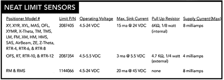
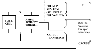
Our standard limit sensors operate via the Hall effect; they detect the position of a magnet that moves relative to the sensor. With the exception of those used in our RM and RMS Series positioners, our limits include the Hall sensor chip, a pull-up resistor, and integral leadwires. Due to space constraints, our RM and RMS stage models have no integral pull-up resistor. They are the open collector type, which means they switch low (sink current) upon activation. See the chart and figure 25 for details. The pull-up resistor provides a fail-safe function; if a limit cable is missing or broken, the controller will see a logic low, preventing motion until the cable is installed or repaired. If our RM and RMS Series positioners are used with controllers that are not of DOVER design, then external pull-up resistors in the motion control electronics may be required.


Figure 25 – Limit Sensor Schematic
The limit switch signals are brought out on the Limit/Encoder connector, which is a sub-mini DE-9-S (socket) connector in most of our stage models (see “Rotary Motor Mount“). While our limit switches can operate at voltage levels of up to 24 volts, their nominal operating voltage is +5V.
PLEASE NOTE THAT THE LIMIT SWITCHES AND ANY ENCODERS SHARE THEIR SUPPLY VOLTAGE! IF YOUR STAGE IS EQUIPPED WITH ENCODERS, USE OF ANY SUPPLY VOLTAGE OTHER THAN +5 VOLTS WILL DAMAGE THE ENCODER. DO NOT USE A LIMIT SWITCH VOLTAGE OTHER THAN +5 VOLTS UNLESS YOUR SYSTEM HAS NO ENCODERS!
Positional repeatability of these sensors is ±1-2 microns (<0.0001 inch) at constant temperature. Homing algorithms should engage the limit sensor briefly and then pull out, stopping at the limit release point, to avoid potential thermal drift incurred by continuous activation. Approaching the sensors at slow, consistent speeds will allow optimal repeatability. Despite the high intrinsic accuracy of our limit sensor, if its trip point is very close to a step or count boundary (especially in low resolution systems), small oscillations in the load position may result in a ±1 step ambiguity in the home position. The use of a once per revolution signal from a rotary encoder in conjunction with the limit switch, or the index mark on a linear encoder, can provide yet more accurate home position repeatability.
DOVER has designed a PC board that allows compatibility with controllers that look for alternate limit sensors (not of DOVER design). This surface mount board fits within the motor mount of most of our stage models, and is directly connected to the DE-9 Limit/Encoder connector. This board has been designed so as to allow our standard DOVER limit switches to achieve compatability with virtually all motion controllers available in the marketplace. Since this board is implemented in surface mount technology, it is not configurable by our customers. If you plan on operating a DOVER stage with a motion controller from another vendor, it is important that you inform the salesperson of the intended controller, or its electrical input requirements, at the time of order. We can also reconfigure stages should you change your motion controller, but this will require that the stage be returned to our Customer Service Department.

