Piezo Actuators. Overview and Limitations
A Piezo actuator, also commonly referred to as a piezo linear actuator, is a device that converts electrical energy directly into linear motion using the piezoelectric effect. This effect occurs when we apply mechanical force and stress to certain materials, such as quartz and ceramics. The stress generates an electrical charge known as the piezoelectric effect. It produces an extension or contraction in the material and a mechanical displacement, which is the basis of the piezo actuator's operation.
The piezo actuator consists of a piezo motor (motion created by applying voltage inverse piezoelectric effect) and mechanical elements which allow the movement of the actuator. To control the movement of the actuator, modern piezo linear actuators are fitted with a controller and position feedback device and manipulated via a computer interface.
Topics:
Piezo Actuator Applications
Piezo actuators are used for their precise control and efficiency in a wide variety of applications ranging from medical diagnostics and DNA sequencing to materials engineering and semiconductor inspection. However, they are often plagued with issues of high cost and limited travel, speed, and bandwidth.
The DOF Objective Focusing Stage with voice coil motor is recommended in place of piezo motor technology to relieve these issues and achieve greater travel (> 5mm) at a substantially lower cost.

Linear Stages
We can configure the right motion solution for your unique application.
Limitations of Piezo Actuators
All translation stages require guideways and a means of actuation to produce motion along the guideways. There are a number of actuation technologies available to choose from, and one of these makes use of the inverse piezoelectric effect. Due to the very low magnitude of this expansion or contraction produced by it, all practical implementations of the piezo effect rely upon either reiteration or amplification to produce useful motion.
Types of Piezo Actuators
There are many configurations of piezo actuators listed below, and we will discuss them in this article:
Piezo Stacks
The inverse piezoelectric effect was first discovered by Pierre and Jacques Curie in 1881. Today, the most common materials used for piezo linear actuators are either barium titanate or PZT (lead zirconate titanate) ceramics. The ratio L/L (change in length to length) for an applied voltage is quite small for a single piezoceramic element, and so most actuators are composed of a large number of thin plates, referred to as a piezo stack. The voltage applied to the piezo stack is distributed to each of the plates within the stack in a parallel configuration.
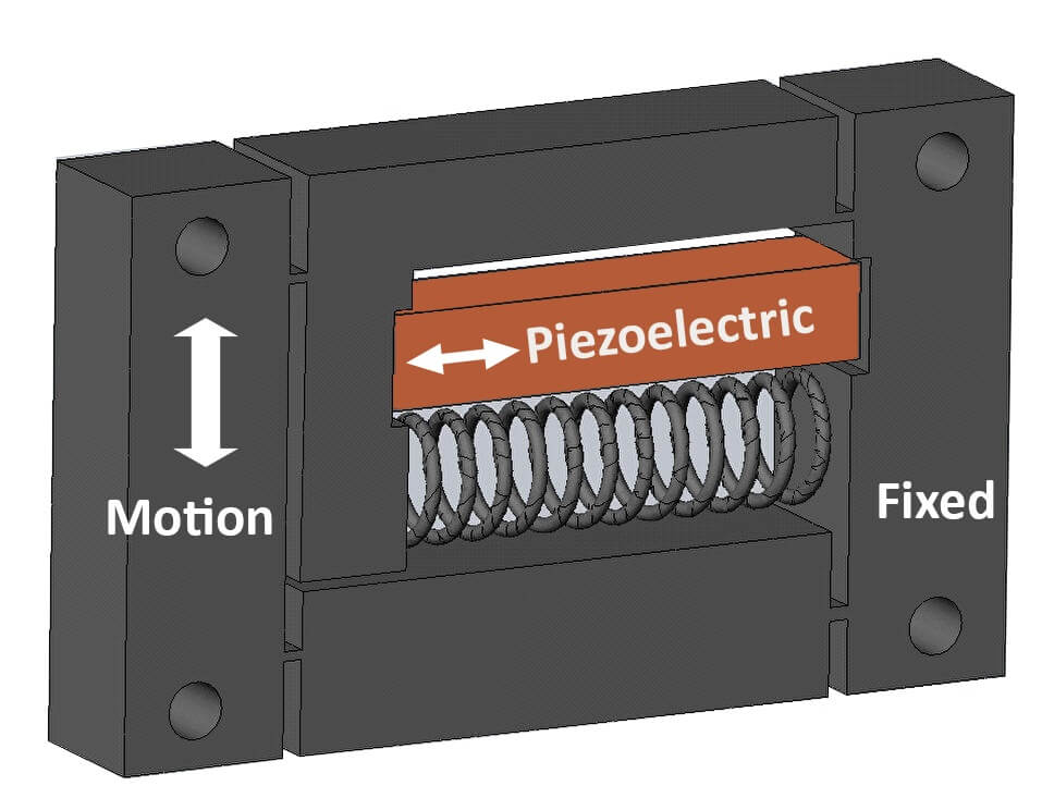
Depending on the nature of the piezo material (soft versus hard), the applied voltage range is typically either +/- 1000 volts for hard or high voltage stacks, or +/- 120 volts for soft or low voltage stacks. Piezo linear actuators by themselves, are fragile and unable to produce force in both directions. These limitations can be significantly reduced if the stack is mounted within a housing and if powerful springs are used to produce a high internal preload.
Housed piezo actuators with internal preload springs are useful, but suffer from several limitations, including:
- Limited Travel. Typical piezo stages range in travel from 10 to 200 microns. The number of plates grows with increased travel, increasing both stack length and cost as travel increases. A stack capable of 200 microns of motion (the most common upper limit among commercially available devices) will typically be about 200 mm long.
- Significant amount of hysteresis or variation of travel versus applied voltage between forward and reverse movement. This can be as much as 15% of full travel.
- Drift problem. The motion in the piezo actuator continues to slowly creep after a position step. While the use of a linear position feedback transducer and a closed loop servo control can overcome hysteresis and drift, compared to the inherent simplicity of an open loop voltage commanded piezo stack, this comes at a considerable added cost and complexity. When operated in closed loop mode, an additional concern arises. The payload mass and the stiffness of the piezo stack produce a high Q resonance, the natural frequency of which can be surprisingly low for realistic tooling and part masses. The high Q of this resonance can complicate efforts to notch it out, and the end result is often that a lower than desired servo bandwidth must be accepted. In general, piezo stages with internal preload and closed loop position feedback can be useful positioners, but will provide limited travel, may be longer and more expensive than desired, and will be limited to moderate servo bandwidths unless the payload mass is quite small.
Piezo Stacks with Mechanical Amplification
The inevitable conflict between the available travel and practical requirements of most applications leads piezo designers to adopt a variety of travel enhancing techniques. One of these is to add a mechanical amplification of the piezo movement to increase travel. To avoid issues such as play and stiction, the mechanical amplification is typically achieved using a flexural hinge with a lever amplification between the input (the end of the stack) and the output (stage moving carriage). The advantages of this scheme are that larger travels can be attained, and that a shorter and lower cost piezo stack can be used. However, the downsides are significant and include a reduction of the allowable load by the lever amplification with the stiffness falling by the amplification ratio squared. More critically, the natural frequency of the combination is reduced by the amplification ratio. This has serious implications for system bandwidth as well as dynamic response.
Bimorphs
Bimorphs are components that consist of a pair of thin piezo elements bonded together with conductive electrodes on the outer surfaces and, in some cases, at the interface between the plates. They function in an analogous manner to a bimetallic strip with voltages of the proper polarity producing a contraction in one plate and an expansion in the other. As a result, the plate bends to one side with amplitudes of a millimeter or more. While they can be used for the positioning of very small payloads, they suffer from very low stiffness and very low load bearing capacity, and are appropriate in a limited subset of positioning applications.
Inchworms
Inchworms incorporate two radial and one axial piezo elements that surround a cylindrical guide rod, and are an innovative attempt to increase travel. In this case, the system control orchestrates a sequence in which the first radial element is clamped, the axial element extends, and the second radial element clamps. The first radial element can then be released, the axial element retracts, and the process repeats, akin to the motion of the insect for which it is named. While remarkable as an idea, the resulting product is always limited to speeds of a few millimeters per second, is fussy to align, quite fragile, has a limited service life, and exhibits “print-through” of the clamp events on the velocity profile. While the technique offers good stability and stiffness at rest, the disadvantages usually predominate.

Resonant Piezo Actuators
Resonant piezo actuator offers extended travel (from millimeters to meters) with moderate resolution and is the most practical implementation of the piezo effect for travels beyond the range of stack actuators. In this design, one or more ceramic fingers are preloaded against a ceramic spar, and piezo elements are used to drive the fingers in an oscillatory motion against the spar. The combination of extension and bending creates an elliptical motion of the tip, which can be used to impart motion to the stage.
The piezo elements are parts of a high-Q, high-frequency, resonant LC tank circuit. The ceramic spar sets the length of travel, and the system has the advantage that when no motion is commanded, the fingers act as a brake and prevent stage motion. When teamed with an appropriate position feedback device, servo loop controller, and linear or rotary bearing guideway, the result is a compact and reasonably effective long-range piezo actuator.
Despite this, the system has a number of disadvantages when compared to direct drive methods using permanent magnets and coils. The dominant issue is that there is significant friction to overcome. This is inevitable, since the fingers must be preloaded against the ceramic, and yet must move relative to it. The greatest problem posed by this friction is that the transfer function has a very large deadband—a range of command voltage for which there is no resulting motion.
Resonant piezo actuators essentially convert a command voltage to a velocity. If these two quantities were strictly proportional, as the current and force in a magnetic drive are, things would be better. But the transfer function turns out to have a friction-generated deadband of several hundred volts. Given that servo electronics is based upon linear control theory, this wreaks havoc with the desire to close a stable, well-behaved loop. Some efforts have been made to compensate for the deadband with a friction bias, but since the friction varies with preload along the travel, no one value will suffice.
The friction also produces wear, which limits the lifetime of the piezo actuator and produces particulates. This wear is more pronounced when a limited region of the travel is used repetitively, which is typical in photonic assembly. The efficiency of these piezo linear actuators is quite low and high device heating can occur if appreciable mechanical energy must be imparted to the stage; this is particularly an issue in vacuum systems. The available force falls off with speed, and for most systems a top speed of ~ 100 mm/sec is required to allow sufficient additional force to overcome bearing stiction. While the fingers do offer a braking function at rest, they have a finite stiffness, and this can lead to unexpectedly low resonant frequencies for moderate-sized payloads. Resonant piezo actuators are the best attempt to date to produce extended travel via the piezo effect, but they can in nearly all cases be surpassed in performance by non-contact magnetic drive.
Piezo Tubes
Piezo tubes consist of a thin-walled cylinder composed of a piezo ceramic with an outer and inner metallized layer. The outer layer is sectioned into four 90-degree quadrants with wire leads as well as a common lead attached to the metal layer on the outer diameter. One end of the tube is fixed and the other end carries a small (tens of grams) payload. The tube body serves as a flexural guideway for the resulting motion. Depending on the polarity and magnitude of the voltages applied to the electrodes, either X, Y, or Z axis translation can be produced, albeit with quite limited travel (a handful of microns, depending on tube dimensions; Z travel is less). Nevertheless, the ability to perform independent three axis motion with a single, very compact actuator/guideway is remarkable. The resolution is extremely fine, and piezo tubes of this type are used in atomic force microscopes with sub-Angstrom resolution.
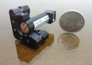
Figure 1: Dover Motion BeamSteer assembly, using Piezo tube
Recommended Articles
Have Questions? Contact Us
"*" indicates required fields