Linear Positioning Systems
A linear positioning system provides precise motion along a linear axis using various techniques, such as lead screws, ball screws, and linear motors. These systems are widely used in fields like life sciences and diagnostics, where they ensure accurate movement for applications such as microscopy, DNA sequencing, and cell analysis. High-precision technologies, including linear encoders and laser interferometers, further enhance system accuracy.
Linear Positioning System Capabilities


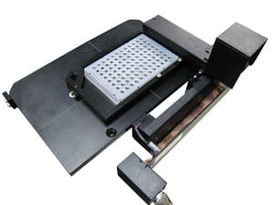
Tip/Tilt Slide Stage Mounted on an XY
- High speed / long travel lower axis stage for sample load and unload
- Smooth & stiff upper axis for high throughput field to field stepping
- Tip / Tilt stages compensate for slide variation & ensure focus

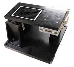
Well Plate XYZ Positioning System
- Hybrid stepper and linear motor combination optimized for price & performance
- Precision linear motor high speed Y axis
- Lead screw based lower X axis and Z lift indexing axes
- Integrated standard well plate carrier

NGS Motion Sub-Assembly
- Stepper based filter changer
- Precision crossed roller bearing XY stages for flow cell positioning
- Linear motor Z stage for objective focusing
- Integrated laser autofocus for high throughput

Point of Care Slide Imaging Subsystem
- Optimized miniature XYZ stage design with built-in controls
- Single slide XY motion
- 5nm resolution encoder feedback

Microscope Linear Positioning System
- DOF-5, 5nm resolution objective focusing stage
- Linear motor XY stage for slide scanning
- Custom structure with built in vibration isolation
The Ideal Linear Positioning System for Your Application
With over 60 years of experience in life sciences, diagnostics, and factory automation, we understand your industry's challenges and offer the flexibility to meet your cost and schedule goals. Whether you need a standard motion product or a completely custom linear positioning system, we’ll work closely with your team to ensure your project meets even the toughest design and budget targets. Our collaborative approach ensures we provide motion solutions that align perfectly with your requirements.
Linear Positioning System Types
Linear positioning systems are categorized based on their technology and application requirements. The main types include:
- Lead screw based systems, ideal for low to moderate accuracy and cost-effective applications. Leadscrew based systems, often utilized in open-loop configurations, manage errors like backlash and thermal expansion, ensuring reliability.
- Linear motor with encoder systems offer higher resolution by eliminating mechanical errors.
- Laser interferometer systems are known for achieving the highest precision by minimizing Abbé and cosine errors through advanced feedback mechanisms.
Each system type addresses specific needs, such as minimizing backlash, managing thermal expansion, and improving geometric alignment, ensuring optimal performance across various industrial and scientific applications. Let's explore the different types of linear positioning systems individually to understand how they address these needs.
Functions of a Positioning System:
Linear positioning systems are used in a variety of applications that require accurate and repeatable motion. Some specific functions include:
- Precise positioning of objects: Linear positioning systems can be used to position objects with a high degree of accuracy. This is essential for many applications, such as microscopy and DNA sequencing.
- Movement of objects: Linear positioning systems can be used to move objects in a straight line. This is useful for applications such as robotics and automation.
- Control of motion: Linear positioning systems can be used to control the speed and acceleration of objects. This is important for applications that require precise control of motion, such as cell analysis and sorting.
Linear Positioning System FAQ
Linear positioning refers to the precise movement of an object along a straight, linear path. It is controlled by mechanisms such as lead screws, motors, and feedback systems like encoders. These components work together to ensure precise, repeatable movement.
Linear positioning is widely used in applications requiring accurate and repeatable motion, such as automation, robotics, and life sciences.
A linear motion system is a mechanical system engineered to move objects precisely along a straight line. It typically consists of multiple components like linear bearings, guide rails, and actuators (such as lead screws, ball screws, or linear motors), which control the motion.
Linear motion systems are used in applications that demand high precision and reliability, such as:
- Microscopy, where accurate stage movement is required to scan samples.
- DNA sequencing that demands precise control for handling and analyzing genetic material.
- Cell analysis and sorting, where linear motion ensures accurate positioning of cells during high-throughput screening.
The three main types of positioning error motions in linear positioning systems are:
- Straightness error: Deviation from the straight path during movement along the intended axis.
- Yaw and pitch errors: Rotational errors around the horizontal (pitch) or vertical (yaw) axis during linear motion.
- Roll error: The twisting motion of the stage around its longitudinal axis, which can affect overall precision and accuracy.
These errors can affect the system’s ability to maintain accurate, repeatable positioning, especially in high-precision applications such as microscopy, DNA sequencing, and cell imaging.
Lead Screw Based Systems
 Low to moderate accuracy systems typically depend on a lead screw or ball screw to provide accurate incremental motion. These systems are often operated open loop via stepping motors; if closed loop operation is employed, it is frequently with a rotary encoder. In either case, the screw is a principal accuracy determining element. Screws exhibit a cumulative lead error, which is usually monotonic in nature, together with a periodic component, which is cyclic and varies over each revolution of the screw. In addition, there can be backlash in a leadscrew nut, which will reveal itself upon direction reversal. Precision positioning stages generally employ either a preloaded ball screw, or a lead screw with an anti-backlash friction nut. Ball screws are preferred for high speed applications, and offer a high natural frequency due to their inherent stiffness. Lead screws with anti-backlash nuts provide very high repeatability at modest cost and are appropriate for most applications. Dover Motion leadscrews are available in both commercial and precision grades, with cumulative lead errors of 0.0001″/inch (1 micrometer/cm) for the precision grade and 0.0004″/inch (4 micrometers/cm) for the commercial grade. Periodic error values are 0.0004″ (10 micrometers) and 0.001″ (25 micrometers), respectively. The above cumulative lead errors correspond to 100 and 400 ppm for precision and commercial grades, respectively.
It is important to realize that using a lead screw with a specified cumulative lead error, periodic error, and repeatability does not ensure that the positioning table will provide that level of accuracy. Among the factors contributing to degrading overall performance are thermal expansion, ambient temperature changes, nut-friction-induced heating, and Abbé error. Both of the latter effects produce different error values depending on the location of the user payload. In the case of lead screw thermal expansion, the position of the nut relative to the stage duplex bearing is important, while for Abbé error, it is the distance from the lead screw centerline to the customer payload.
As mentioned above, angular errors in the stage ways degrade linear positioning accuracy through Abbé error. X-Y Tables have an additional parameter that impacts accuracy to a substantial degree: orthogonality, or the degree of squareness between the two axes. This parameter is held to less than 50 arc-seconds on our commercial grade tables and less than 20 arc-seconds for precision models. For the latter case, a 300 mm travel corresponds to 30 microns of error due to orthogonality alone. We can, upon request, prepare tables that are square to within 10 arc-seconds; note, however, that trying to get the level of orthogonality lower than the value for yaw has limited meaning. Custom systems (typically air bearing designs) can hold orthogonality errors to below 2 arc-seconds. Another error source in systems with two or more axes is opposite axis error, which results when one axis has a straightness error. It is the job of the lead screw or encoder on the other axis to provide accuracy in this direction, but since they are on two separate axes, this error is not corrected. Cosine error, or inclination of the leadscrew or encoder to the ways, is usually slight, but grows in importance with short travel, interferometer based stages. All of the above geometry errors are amenable to cancellation through mapping.
Linear Motor with Encoder Systems
 Use of a linear motor with an encoder eliminates concern over the lead screw cumulative and periodic error, as well as friction induced thermal expansion. In many systems, the lead screw can be dispensed with altogether and replaced with a non-contacting linear motor. With intrinsic accuracies on the order of 5 microns per meter, linear motor with encoder stages offer a significant increase in accuracy over lead screw-based systems, as well as much higher resolution (typically 0.1 to 1 micron). A number of error sources remain, however, and are often overlooked when specifying an encoder. The single largest error is often Abbé error, which can easily degrade accuracy by tens of microns. With a thermal expansion coefficient of ~10 ppm/degree C, linear encoders must be carefully controlled thermally to utilize their potential accuracy. An ambient temperature change of 1 degree C produces a 10 micron per meter error, double the encoders intrinsic 5 micron per meter accuracy. Contacting encoders are convenient, but read-head wind-up can be about half a micron, and higher if rubber sealing wipers are left in place. Non-contact encoders eliminate read-head wind-up, but can have tighter alignment requirements during installation. The encoder resolution itself defines an error source; a 1 micron resolution encoder moving from zero to +5 microns may display +2 microns when the read-head is actually at +2.7 microns, resulting in a 0.7 micron worst case error. Increasing the resolution below 2-5 microns generally requires electronic interpolation, which can also contribute low-level errors. In X-Y tables, each encoder fails to detect horizontal run-out in the other axis (opposite axis error), thereby ignoring translation along its measurement axis of potentially large magnitude (1 to 10 microns, depending on stage design, precision, and travel). Linear encoders are also incapable of correcting for orthogonality errors, which can range from 1 to 20 microns, again dependent on linear motor stage design, precision, and travel. Properly specified, linear encoders can significantly improve system accuracy, particularly if mapping is employed, but their limitations are frequently understated.
Laser Interferometer-Based Systems
Laser interferometers are the ultimate position feedback device. They offer very high resolution, typically 10 nanometers in single pass and 5 nanometers in double pass. Intrinsic accuracy is better than 1 ppm for unstabilized sources, and as high as 0.01 ppm for stabilized designs. Abbé error can be virtually eliminated by appropriate location of the retroreflector or plane mirrors. Opposite axis error and table orthogonality error, intrinsic to encoders, can be eliminated in X-Y tables by the use of two plane mirrors (see Interferometer Feedback Systems). Among the barriers to achieving the very high intrinsic accuracy possible with laser interferometers is the variability of the speed of light in air. This value, constant only in a vacuum, is a function of atmospheric pressure, temperature, and humidity, as well as the concentration of other trace gases. The impact amounts to about 1 ppm per degree Centigrade, 0.4 ppm per mm-Hg pressure, and 0.1 ppm per 10% change in relative humidity. In actuality, the relationship (the Edelin equation) is non-linear, but the above linear approximations are valid for small changes near S.T.P. (760 mm-Hg, and 20 degrees C). Compensation for varying atmospheric conditions can be performed by manual entry, or by automatic sensing and correction term calculation, using precision environmental sensors and the system computer. Since atmospheric effects influence the entire air path between the polarizing beamsplitter and retroreflector (or plane mirror), it is important to minimize the “dead path” between the positioning table and the stationary beamsplitter.
Assuming that the beam path has been chosen so as to eliminate Abbé error, the remaining error sources (other than atmospheric effects) are thermal expansion of the user’s part, the positioning table parts, and the base which mounts the table relative to the optics; differential flexing of the table top as it travels; cosine error; and imperfect squareness and flatness of the plane mirrors in X-Y assemblies. The use of “L” mirrors can replace two adjustable plane mirrors with a single glass L mirror; while this avoids concern about misadjustment, neither case can readily assure squareness below the ±1 arc-second level. This limits X-Y systems to a minimum of 5 ppm inaccuracy due to this effect alone; over a 300 mm travel, this accumulates to 1.5 microns. Single-axis systems, which do not have squareness to contend with, can achieve overall accuracies approaching several ppm (1-3 microns/meter), assuming exacting thermal management and atmospheric compensation, as well as beam angle trimming to minimize cosine error. At this level, positioning system design becomes a fairly elaborate exercise in HVAC (heating, ventilation, and air conditioning).
To illustrate the degree to which thermal issues complicate system design, consider a 300 mm travel single-axis table which seeks to achieve “tenth micron accuracy”. One tenth of a micron over 300 mm is equal to 0.3 ppm. Recall that atmospheric compensation for laser interferometers is 1 ppm per degree C and 0.4 ppm per mm-Hg pressure. There will also be ~350 mm of base material (we will presume granite) between the table center and the stationary beamsplitter. The thermal expansion coefficient of granite is 6.3 ppm per degree C. If we choose to allocate our “error budget” of 0.3 ppm, assigning 0.1 ppm to atmospheric temperature, 0.1 ppm to atmospheric pressure, and 0.1 ppm to granite thermal expansion, then we have the following result: air temperature must be measured with 0.1 degree C absolute accuracy; pressure must be measured to within 0.25 mm-Hg accuracy; and the granite must be maintained at a constant temperature within 0.02 degrees C.
This analysis neglects thermal expansion of the user’s part or the positioning table top, as well as cosine error, humidity changes, table top differential flexure, etc. Temperature changes in the interferometer optics alter the path length of the reference beam, introducing another error source, although specialized optics are available which reduce this effect. If the user’s part is not maintained at exactly 20 degrees C, back correcting to that temperature requires precise knowledge of its thermal expansion coefficient, which is rarely available. Proper estimation and inclusion of all these error sources further exacerbates the thermal control requirements, often raising them to largely unachievable levels. Given that a fairly expensive laser interferometer fails to approach the needed accuracy levels in this application, the application of appropriate skepticism to advertising claims for stage accuracy is warranted.
Linear Positioning System Resources

Through concurrent and collaborative engineering, Dover Motion developed a compact custom XYZ stage motion solution to produce high-precision cell imaging in parallel with the instrument design.

Dover Motion defined the motion system requirements and tightly integrated the hardware in the overall instrument design, enabling the client to get the funding they needed to continue their project.

To reduce the overall size, Dover Motion used compact stepper motors with integrated lead screws. Placing the motors within the stage structure enabled all wiring to be concealed and to exit at the bottom of the stage.