XYZ Stages
An XYZ stage, also known as a multi-axis linear stage, is a powerful positioning tool that delivers micrometer-level accuracy across three linear axes: X (horizontal), Y (horizontal), and Z (vertical). This enables precise and repeatable movement of objects in three dimensions, making it a vital component in a wide range of industries.
XYZ stages are instrumental in advancements across various fields, particularly in life sciences and diagnostics. From fluorescence in-situ hybridization (FISH) to DNA sequencing, digital pathology, proteomics, and live-cell imaging, these stages ensure the accurate positioning and manipulation of samples, critical for reliable results.
XYZ Stage Products
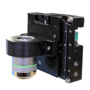
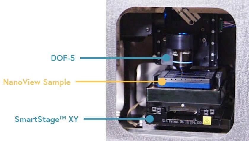
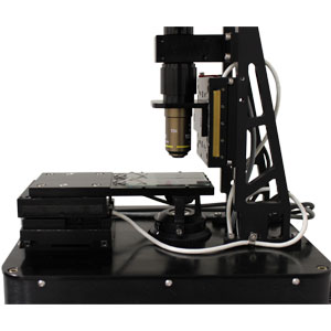
The DOF Series Dover Objective Focusing Z stage has been optimized for optical microscopy applications. Eliminates alignment headaches.
| wdt_ID | Travel | 5 mm |
|---|---|---|
| 1 | Resolution | 1.25 nm |
| 2 | Repeatability | < 50 nm |
| 3 | Bandwidth | > 225 Hz |
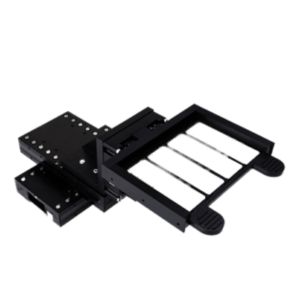
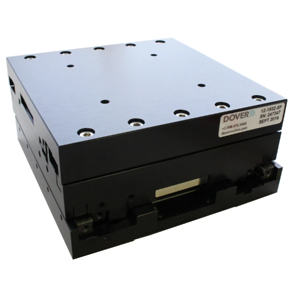
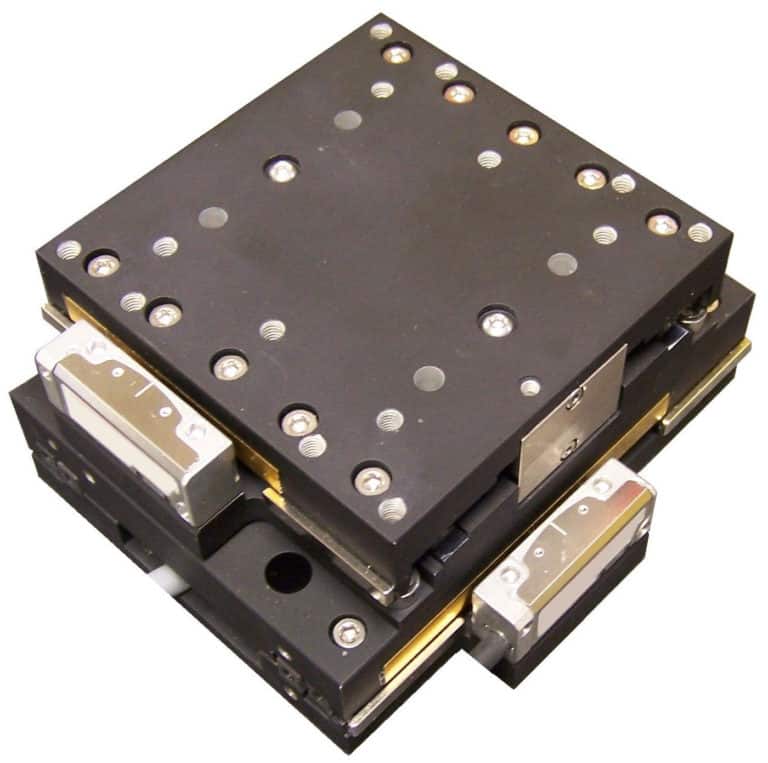
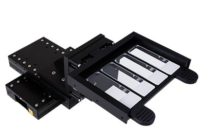
The SmartStage XY Linear Positioner offers high performance and includes an innovative built-in controller right inside the stage.
| wdt_ID | Travel | 50 - 200 mm |
|---|---|---|
| 1 | Accuracy | ≤ 10 μm |
| 2 | Repeatability | 0.8 μm |
| 3 | Payload | 10 kg |
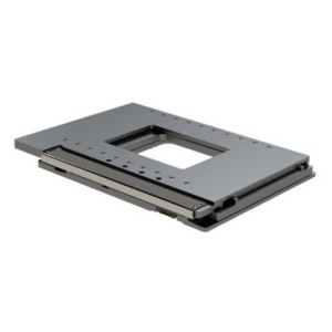
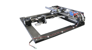
Coming Soon! The SmartStage™ Open Frame stage is the first open aperture linear motor stage with an embedded controller.
| wdt_ID | Travel | 115 x 75 mm |
|---|---|---|
| 1 | Accuracy | ≤ 10 μm |
| 2 | Repeatability | 0.8 μm |
| 3 | Payload | 10 kg |
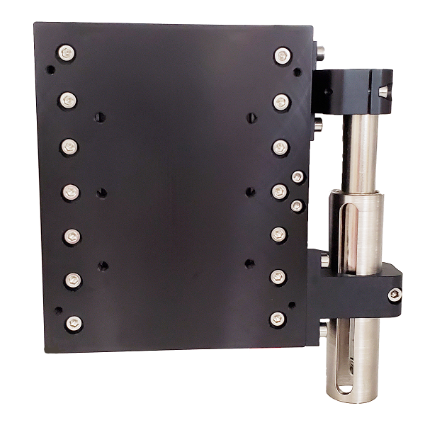
The SmartStage™ Z-50 Nanopositioning stage provides a unique combination of travel distance, and precision, for Z stage applications.
| wdt_ID | Travel | 50 mm |
|---|---|---|
| 1 | Resolution | 5 nm |
| 2 | Accuracy | 10 μm |
| 3 | Repeatability | .8 μm |
The SmartStage XY Monolithic is a positioning stage in a low-profile XY form factor, designed using stiff crossed roller bearings for superior performance.
| wdt_ID | Travel | 50 - 75 mm |
|---|---|---|
| 1 | Accuracy | 12 μm |
| 2 | Repeatability | 0.8 μm |
| 3 | Payload (kg) | 10 kg |
The Miniature Linear Stage – MMX™ is a compact linear stage with an actuator specifically designed to fit inside benchtop instruments and small spaces
| wdt_ID | Travel | 25 - 150 mm |
|---|---|---|
| 1 | Accuracy | < ± 3 μm |
| 2 | Repeatability | < ± 0.4 μm |
| 3 | Payload | 10 kg |
Custom XYZ Stage Options
With over 60 years of expertise in motion optimization for objective focusing and sample movement in X, Y, and Z directions, we understand the unique challenges OEMs face. We recognize that different designs, cost considerations, and schedule targets may require customizations beyond our standard line of XYZ stage products. Whether it's modifying our existing solutions or creating a completely new design, we offer customizable options to meet your project needs.
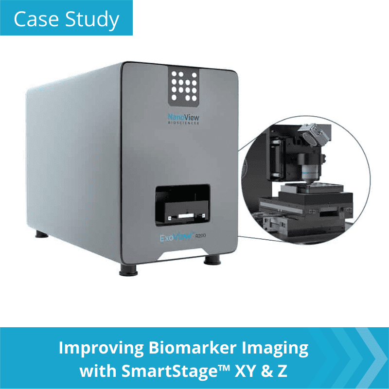
In our new video and case study, discover how Dover Motion's integrated solution for the X, Y, and Z axes allowed NanoView Biosciences to enhance throughput and reliability in their next-generation instrument.
Determining the XYZ Motion Systems Architecture in an Automated Microscopy Instrument
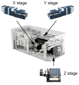
Once the optical imaging elements are selected, the XYZ stage motion system architecture can be finalized. A typical field of view is much smaller than the sample being imaged. Thus, in order to image an entire sample, either the sample or the camera/objective will need to move along two perpendicular axes (XY). In addition, in order to properly resolve the image, the distance between the magnification objective and the camera (or image sensor) needs to be precisely adjusted. This is referred to as the Z axis. The Z axis is typically vertical and motion along it, to move the sample into the imaging field of view, occurs perpendicular to the XY plane.
There are three common configurations of the XYZ motion hardware. Selecting the best one depends upon the particular application’s complexities:
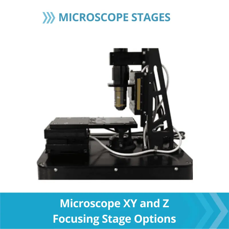
1.The XY stage moves the sample below a Z stage that is moving the objective or camera.
This is the most common configuration of XYZ stage motion. The benefit of this approach is that the image becomes stable after motion more quickly because it is only moving on one axis. This means it can be mounted to a sturdy structure instead of a stack of three moving axes whose resonances need to damp.
During sample loading, the objective can be moved vertically away from the sample mounting area, which makes changing samples easier. Also, Abbe errors are reduced because the overall stack is shorter.
2. Three motion axes move the object being imaged in X, Y and Z directions while the camera and objective remain stationary.
In this situation, the camera is very stable because it is mounted to a rigid surface. The drawback is that the travel required for the Z axis may be longer because the objective-to-imaging sensor distance is fixed. Typically, it requires less travel to move the objective with respect to the imaging sensor or camera.
3. The objective or camera is moved in X, Y and Z directions, while the sample remains fixed.
This approach works best when imaging small parts such as a microscope slide. As part size increases, the complexity of this approach also increases. Larger travels tend to require multi-axes to support a beam that has the vertical focus axis with both the imaging sensor and objective mounted to it.
With over 60 years of expertise in motion optimization for objective focusing and sample movement in X, Y, and Z directions, we understand the unique challenges OEMs face. We recognize that different designs, cost considerations, and schedule targets may require customizations beyond our standard line of XYZ stage products. Whether it's modifying our existing solutions or creating a completely new design, we offer customizable options to meet your project needs.
In our new video and case study, discover how Dover Motion's integrated solution for the X, Y, and Z axes allowed NanoView Biosciences to enhance throughput and reliability in their next-generation instrument.
Configuring the XY Stage and Z Axis
Determining the best motion technologies to configure the XY stage and Z axis depends on carefully considering the attributes of each in light of your requirements and budget. What focusing technology (software v. tracking laser autofocus) will you be using? What are your requirements for resolution, speed, accuracy and bandwidth? What frequency of images is required (do you require a single image per step or a continuous scan)? What are the size and shape of your samples and camera?
Please keep in mind though, that if the best technology still requires modification to suit your application, that is where Dover Motion excels. We have a track record of meeting focusing challenges at the edge of current capabilities in the industry.
Additional XYZ Stage Resources
FAQ
An XYZ stage is a type of linear positioning system that provides precise and controlled movement along three linear axes: X (horizontal), Y (horizontal), and Z (vertical). This allows for three-dimensional positioning of objects with high accuracy and repeatability. Each axis of a linear stage must constrain the six degrees of freedom (X, Y, Z, roll, pitch, and yaw) of the payload to only one, producing translation along a straight line.
XYZ stages are a vital component in a wide range of automated applications across various industries, including:
Scientific Research: Microscopic analysis, precise manipulation of samples in life sciences (like cell cultures or DNA analysis), and even 3D printing processes that require meticulous layering of materials.
Medical Technology: Imagine robotic surgery systems that require delicate instrument manipulation, laser cutting equipment for medical devices that demands pinpoint accuracy, or even diagnostic equipment performing intricate scans. XYZ stages play a crucial role in these applications.
Manufacturing: Automated assembly lines rely on XYZ stages for precise component placement, material handling tasks benefit from their controlled movement, and quality control processes often utilize XYZ stages for consistent and accurate sample positioning.
Each axis of an XYZ stage is driven by a separate motor and mechanism, such as a screw drive or belt drive. These mechanisms constrain the movement of the platform to a single direction, ensuring precise linear motion.
Common types of linear bearings used in XYZ stages include:
- Ball and crossed roller bearings: Offer high load capacity and smooth motion.
- Recirculating bearings: Provide high precision and low friction.
- Cam followers or vee wheels: Used for simpler applications requiring lower load capacity.
- Air bearings: Offer exceptional smoothness and low friction, ideal for high-precision applications.
XYZ stages operate on a three-axis system and allow engineers to achieve precise movement in the X, Y, and Z directions. These stages consist of linear motion components, such as friction screws, ball screws, belts and pulleys, racks and pinions, piezo actuators, and linear motors, which work together to facilitate motion control.
Each of the X, Y, and Z axes in an XYZ stage is equipped with its own motor and controller. These motors drive the linear motion components to achieve the desired direction of movement. The controllers provide the necessary commands and signals to the motors, ensuring accurate positioning and seamless motion. High-resolution linear encoders can be integrated into the XYZ stage for applications requiring
XYZ stages are essential tools in a variety of life science applications. They enable precise positioning for tasks like:
-
- Fluorescence in-situ hybridization (FISH): Studying cellular structures and genetic material.
- DNA sequencing: Automating and optimizing instruments for accurate nucleotide identification.
- Digital pathology: Analyzing tissue morphology and cell morphology for disease diagnosis.
- Proteomics: Investigating protein structures, functions, and interactions.
- Single cell imaging: Studying individual cells for behavior, morphology, and function.
- Live cell imaging: Observing dynamic cellular processes in real time.
- 3D metrology: Measuring objects and surfaces in three dimensions for quality control and inspection.
With applications spanning such diverse fields, Dover Motion offers a wide range of XYZ stages designed to meet the specific needs of your industry. Our stages are renowned for their:
- High precision and accuracy: Ensuring consistent and reliable performance in your critical tasks.
- Durability and reliability: Built to last in demanding environments.
- Variety of travel ranges and load capacities: A perfect fit for any application, from handling delicate samples to heavier components.
- Customizable options: Tailored to your specific requirements, ensuring seamless integration into your existing systems.

