Laser Processing
Laser Processing
Many positioning applications use an XY stage to produce relative motion between a client’s part and an optical system. Many of these cases involve an upward flow of information towards a camera or sensor, such as in an automated imaging or focusing application. Laser processing is when the information flows downwards with an energy source—a laser—that marks, alters the properties of, or removes materials from a client’s part.
Applications for Laser Processing
The action performed by the laser varies with the application and is a function of the laser’s power, wavelength, and output type (pulsed or continuous). In laser marking, the laser alters or removes a shallow layer at the surface of the material (or a thin coating applied to the material), to generate a mark for subsequent visual, machine vision, or bar code identification.
In laser annealing or sintering, the laser power causes a transition in the basic material properties on the surface of the client’s part. These transitions can be focused on small spots or they can be timed and positioned to uniformly process a large area. High-precision, constant-velocity motion with on-the-fly laser triggering is required if a large area is to be uniformly processed with no missed or doubly exposed zones.
Laser machining or cutting uses high laser power to remove materials from the customer part. Laser machining can operate at the very macro-level such as cutting sheet metal, as well as at the very micro-level like the laser machining of cardiac stents.
On Axis Beam Delivery
In the simplest configuration of a laser processing motion system, all motion is provided by the positioning stages and the beam delivery optics are described as “on-axis,” meaning there is no beam steering element such as a galvo. You can achieve very high precision in systems with on-axis optics, but throughput will be a function of the acceleration and top speed of the positioning axes.
Three different physical arrangements are possible with on-axis optics and simple XY movement:

- Fixed optics with the part moving in X and Y
- Optics moving in one axis, while the part moves in a perpendicular axis
- The part remains stationary, while the optics moves in both X and Y
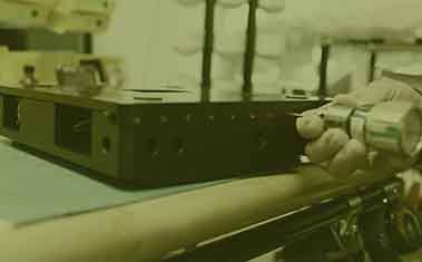
These approaches are typically chosen when the beam delivery optics have a high numerical aperture, when the laser power is high, or when it is critical that the beam remain precisely perpendicular to the work piece at all times. They offer the highest optical performance, smallest spot sizes, and highest positioning accuracy, but also tend to result in lower throughput. Figure 1 shows how an OEM customer used an XY stack of 2 Dover AirGlide™ stages for the laser processing of LED substrates.
More Axes Means More Motion
In addition to simple Cartesian XY and Z axis motion, one or more rotary axes can be added to increase the number of degrees of motion. The ultimate system includes 3 linear axes (X, Y, and Z), as well as 3 rotational degrees of freedom (roll, pitch, and yaw). An example of such a system is the six-degree-of-freedom air bearing positioning system we designed to laser machine tiny dimples in the spherical, frozen deuterium/tritium targets for a laser fusion system at Lawrence Livermore National Laboratory.
Working with Galvo Scan Heads
All systems based on galvos are difficult to scale to high powers, since it is challenging to create mirror coatings that maintain very high reflectivity over a large angle. At high power, anything less than near-perfect reflectivity can destroy the mirror. Galvo-based systems are also counter-indicated when very small spot sizes are required. Their substantial benefits in throughput, however, make them ideal for a variety of low to moderate power systems, with moderate to large spot sizes.
How and Why to Use F-Theta Lenses
A galvo-based scan head can be added to the optical system when higher throughput is essential. In an XY galvo scan head, a pair of rotating mirrors allows the laser beam to be steered in 2 axes at very high speed. The servo bandwidths of traditional XY stages are typically at or below 200 Hz, but galvo bandwidths can exceed 5 kHz for small mirror diameters.
The natural focal plane of a two-axis galvo is a section of a sphere. Adding an optical element called an “F-Theta” lens alters the focal point as a function of field angle, planarizing the focal plane and linearizing the field. Telecentric F-Theta lenses are a variant F-Theta lens that ensure that the beam remains perpendicular to the part throughout the field.
F-Theta lenses can handle fields of view of 30 to 150 millimeters, and provide spot sizes of 50 to 100 microns. A traditional XY positioning stage can be used to provide additional travel for client parts that exceed the field of the F-Theta lens. This stage typically just indexes from one galvo field to another, but commercial motion controllers are now available that seamlessly integrate a macro XY stage with micro, high-speed XY galvo motion. This allows the laser to operate continuously as both the XY stage and the galvo are in motion. This technique, called “spectral decomposition,” analyzes the motion path in real-time and sends larger stroke, lower-speed motion commands to the XY stage while sending smaller stroke, very high-speed motions to the galvo.
Z Axis Focusing Lenses and Laser Savers
 F-Theta lenses become very expensive as the field size increases. In addition to adding an XY stage to address larger fields, another strategy is to add a very high-speed Z axis focusing lens before the primary optics and galvo. This lens is typically the negative lens portion of a Galilean beam expander, and it allows the focal plane to be planarized across the field without the need for a large F-Theta lens.
Z axis focusing lenses permit large planar fields of view of up to one square meter, and reasonably small spot sizes of 20 to 60 microns. However, they require large mirrors that reduce system bandwidth. An additional drawback of a Z axis focusing lens is that as you move away from the center of the field, the laser beam departs from perpendicularity and the laser spot also becomes increasingly elliptical.
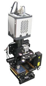
Dedicated laser repair systems called “savers” are used in the production of flat panel displays to improve production yields. Savers zap out any pixels that are stuck on and would otherwise produce a distracting white dot in the display. A photo of a Gen 7 air bearing gantry for a laser saver, with dual laser heads is shown in Figure 2.
Building the Right Laser Processing Solution
Dover Motion has extensive experience with large gantry positioning systems for laser savers, and with air bearing, direct drive technology that ensures ultra-reliable, 24/7 operation. For more than 50 years, we have been collaborating with our clients to build them the right motion system for their laser processing needs. Contact us today to learn how we can work together on your next project.